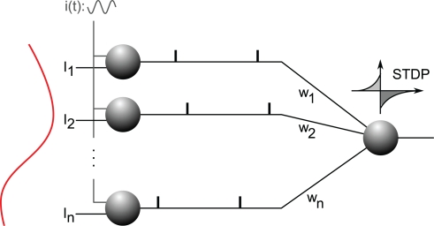
Figure 8.
Analog-to-phase conversion. Excitatory afferents 1…n are shown on the left. They receive static input currents I1…In. (plotted on the left) and a common oscillatory drive i(t), which leads to a current-to-phase conversion: the stronger the current, the earlier the afferent fires during the oscillation cycle. All the afferents are connected through plastic synapses with weights w1…wn, to one downstream neuron equipped with STDP. This neuron will gradually become selective to the spike wave corresponding to the repeating current pattern (see Figure 9). Figure is modified from Deco et al. (2011).

