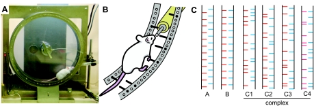
Fig. 1.
The wheel and peg pattern. A: photograph of the running wheel with a mouse actively running to obtain water at the water spout protruding between the right and left pegs. The wheel was turning clockwise, driven by a motor set behind the wheel. The mouse was drinking water while running. The photograph was taken with the touch sensor detached from the wheel to allow viewing of the mouse (see Fig. 3D for an illustration of the wheel with the sensor attached). B: schematic drawing showing a running mouse drinking water from the spout. C: peg patterns used in this study.

