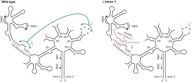
Figure 7.
Model of inhibited intron 2 splicing. The typical six-domain structure of group II introns is shown schematically (1,2,48) for the wild type (left) and the Δ intron 1 mutant (right). The sequence of the junction between exon 1 and exon 2 is shown in red and its possible base pairing with the ζ bulge in domain I (DI) is indicated in the structure for the Δ intron 1 mutant. This base pairing would disrupt the essential tertiary interaction between ζ and ζ′, a GAAA tetraloop in domain V (DV). Exons 2 and 3 are shown in blue, the tertiary interaction between ζ and ζ′ is depicted in green. EBS: exon-binding site; IBS: intron-binding site.

