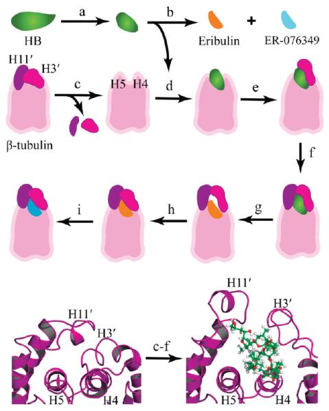
Figure 2.
Modeling the HB binding site. Top three rows: stepwise approach used to model the binding modes. (a) The crystal-based structure of HB was subjected to molecular dynamics, and folded conformations were selected for docking studies. (b) Eribulin and ER-076349 structures were generated from the HB folded conformations. (c) H3′ and H11′ loops were removed from a β-tubulin model to unmask the HB binding site for ligand docking. (d) HB was docked and refined. (e) The H3′ loop was reattached to β-tubulin, and the protein–ligand model was refined. (f) The H11′ loop was reattached to β-tubulin, and the atom–atom interactions were optimized to yield the HB binding model. (g) Eribulin was docked based on superimposition of the common macrocycle shared with HB. (h) Constrained simulations were used to fold the H3′ and H11′ loops onto eribulin. (i) ER-076349 was docked. Bottom row: cartoon rendering showing the key secondary structures of the HB binding site and the conformational changes associated with HB binding. The β-tubulin is rendered in purple ribbon, and HB is shown in ball-and-stick with carbon, oxygen, and hydrogen atoms colored green, red, and white, respectively. Left panel: The protein fold in the 1JFF β-tubulin structure shows the packing of the H3′ and H11′ loops onto helices H4 and H5, which occludes the HB binding site. Right panel: The protein fold in the HB binding model shows the conformational switch of the H3′ and H11′ loops upon HB binding.

