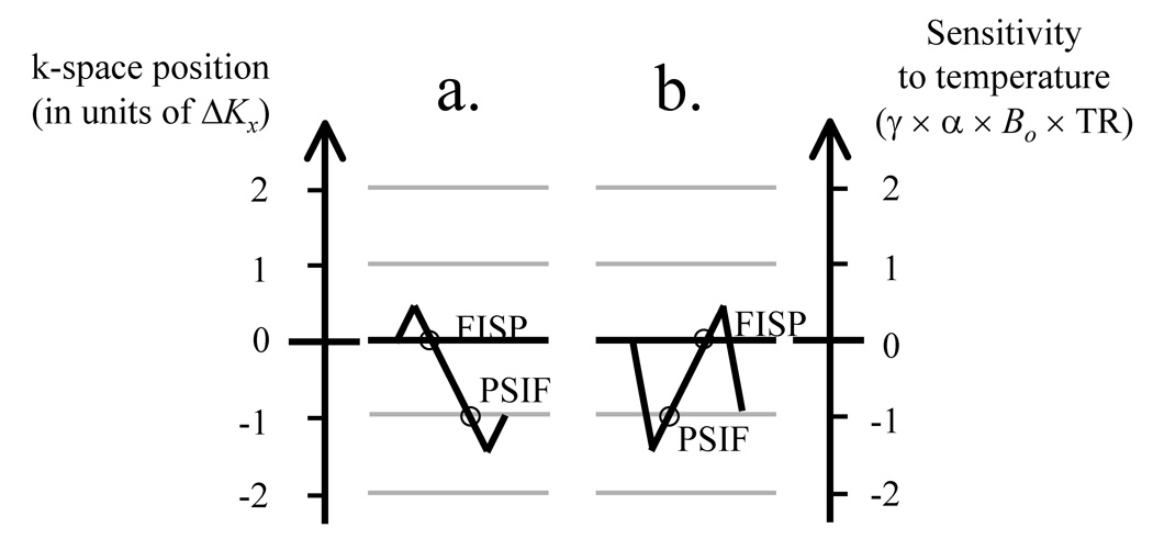
Fig. 3.
a) Effects of the readout waveforms from Fig. 2a are further described here. The gradient lobes in Fig. 2a cause a move along the ‘k-space position’ axis from 0 to +0.5ΔK, then to −1.5ΔK, and then to −1.0ΔK. A displacement of ΔK corresponds to at least the full width of a k-space matrix, to avoid signal overlap between consecutive pathways. The trajectory finishes at a position −1.0ΔK, and samples the FISP at 0 and then the PSIF at −ΔK along the way. b) The waveform in Fig. 2b causes a move from 0 to −1.5ΔK, then to +0.5ΔK, and finally at −ΔK. Note that, in this case, The PSIF is sampled first. At least in principle, waveforms that sample any number of desired pathways could be designed.

