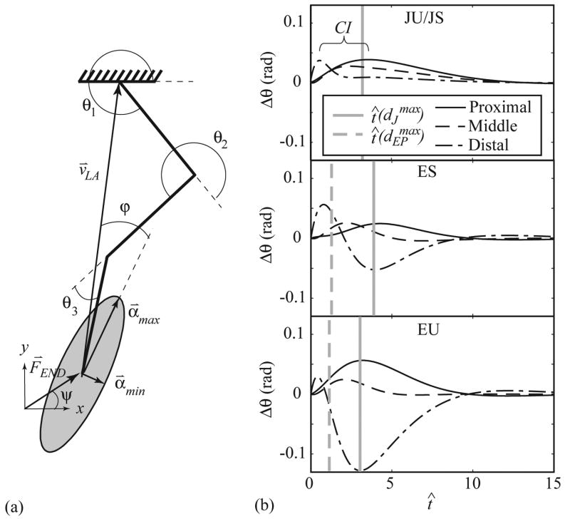
Figure 1.
Model diagram with example endpoint ellipse (A). Three-link model (heavy black lines) with generalized coordinate system (θ⃑ = [θ1, θ2, θ3]T). The limb axis, v⃑LA, is directed from the endpoint to the proximal joint. The endpoint stiffness (kR_END) and viscosity (kB_END) ellipses are characterized by the angle ϕ between the limb axis and direction of maximum stiffness, α⃑MAX. The direction of minimum stiffness is α⃑MIN. Model responses (B) (top: JU/JS, middle: ES, bottom: EU) are shown for a perturbation applied in the x direction (ψ = 0°). The time of maximum endpoint (dashed gray line) and maximum total joint (solid gray line) displacements are indicated.

