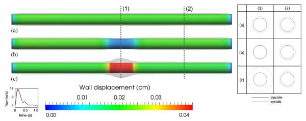
Figure 6.
Simulated wall displacement for the idealized cylindrical model. (a) The case of uniform Young's modulus (uniform case) as in Figure 5(a); (b) The case of larger Young's modulus (stiffer case) in the middle as in Figure 5(b); (c) The case of smaller Young's modulus (softer case) in the middle as in Figure 5(c). Notice both ends were held fixed for all three cases. Overlays are warped vessel wall by nodal displacements (magnified three times for ease of visualization). Labels (1) and (2) mark the locations where radial deformations are probed. The table on the right shows the cross sections of these locations (also magnified three times) at end diastole (black) and peak systole (gray).

