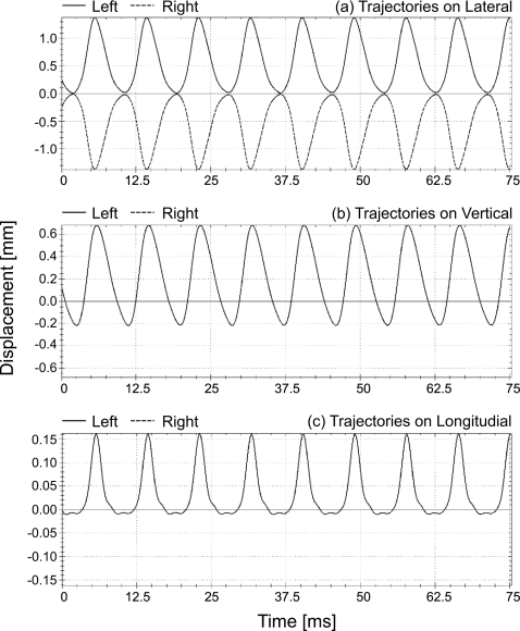
Figure 9.
Simulated symmetrical trajectories in lateral direction (upper figure), vertical direction (middle figure), as well as longitudinal direction (lower figure) of two opposing mass elements (dotted lines for the mass element m2,3 on right side, solid lines for the mass element m7,3 on left) which are situated at third plane and second cross-section in the symmetrical 3DM.

