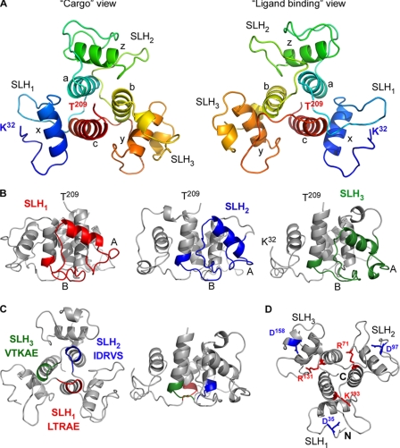
FIGURE 2.
The crystal structure of SapSLH. A, two different views of the SapSLH pseudo-trimer. Each SLH domain is noted, as is the N and C terminus and the six major helices (a, b, c, x, y, and z). The left panel shows the structure from the C terminus, which projects out of the page and away from the SLH domains, and is termed the “cargo” view. The right panel shows the ligand binding surface of the SLH-domains. B, lateral views of the SapSLH crystal structure, each SLH domain (as annotated by NCBI) is colored accordingly. The central core of helices a, b, c is not part of the annotated SLH domain. C, conserved ITRAE motifs of each SLH domain are colored to show their location and are positioned between each pseudo-trimer at the bottom of helices a, b, and c. D, side chains and position of Asp35, Asp97, Asp158, Arg71, Arg131, and Lys193 are highlighted. Charged groups within these residues are in close proximity.

