. Author manuscript; available in PMC: 2012 Aug 15.
Published in final edited form as: J Neurosci Methods. 2011 May 11;199(2):199–207. doi: 10.1016/j.jneumeth.2011.05.004

Fig. 1.

Fig. 1

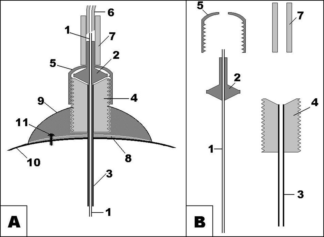
Schematic depiction of microinjection setup, which uses an injector and a guide cannula for acute experiments. (A) assembly; (B) separate parts.
  1. metal tubing of microinjector;
  2. plastic part of microinjector;
  3. metal tubing of guide cannula;
  4. plastic pedestal of guide cannula with thread;
  5. plastic cup with thread matching thread of guide cannula;
  6. thick-wall low-volume Teflon tubing;
  7. PVC connector;
  8. cyanoacrylate;
  9. dental cement;
  10. skull bone;
  11. jeweler’s screw.