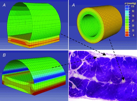
Figure 6. Three-dimensional modelling of the lymphatic vessel wall.

Stress distribution maps obtained through finite element modelling of diaphragmatic initial lymphatics located as indicated on the microphotograph of the transverse section of the diaphragm, panel D. A, immediately beneath the mesothelium: the ellipsoidal superficial vessel is limited mostly by a thin wall of lymphatic endothelium plus pleural mesothelium and lies on a diaphragmatic muscular/tendinous support. B, deeper in the submesothelial tissue: this intermediate vessel is only partially delimited by a thin wall, most of the lateral surface being surrounded by the muscular/tendinous tissue. C, among the diaphragmatic muscular/tendinous fibres surrounded by an isotropic tissue and with a circular cross sectional area (modified from Moriondo et al. 2010). The circumferential stress (σ) distribution is identified by colours on a scale from red (low stress) to blue (high stress) as indicated by the colour scale in C. Vessel tensile stress was higher in submesothelial superficial (A) and intermediate (B) vessels which underwent the greatest deformation. In deeper circular vessels (C) surrounded by stiffer tissue, wall tension was lower and homogeneously distributed over the entire surface.
