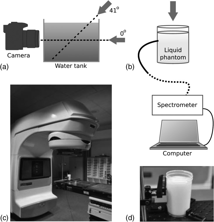
Figure 1.
Schematics of the experimental setups. (a) A water tank and camera where arrows indicate the irradiation direction of the linear accelerator. (b) The cylindrical scattering phantom with the fiber bundle connected to a spectrometer. (c) The linear accelerator with a phantom placed in the target region. (d) A photograph of the cylindrical scattering phantom.

