
Figure 5.
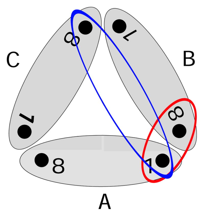
Scheme of the trimer complex and the included inter-monomer couplings: The grey ellipses represent the single monomers A–C. There are two different 1–8 couplings between different monomers. The red ellipse describes the coupling between pigment 1 and the closest BChl 8 of a neighboring monomer (also depicted as 8B). Furthermore, the blue ellipse describes the coupling between pigment 1 and the more distant pigment 8 of the third monomer. Because of symmetry there is only one 1–1 coupling.