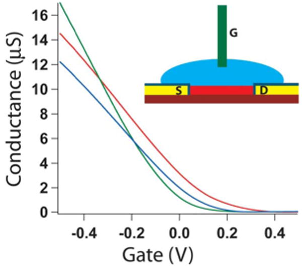
Fig. 5.

Conductance versus water-gate voltage for three representative NWFET devices. Inset: Scheme representing experimental setup, which includes: (red) NW, (yellow/navy) passivated contact electrodes, (blue) electrolyte solution, and (green) Ag/AgCl reference/gate electrode.
