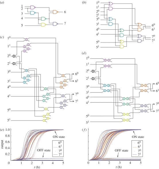
Figure 4.
Compiling boolean logic circuits. (a) A sample circuit with six gates. (b) Translation into an equivalent dual-rail circuit with 12 gates. (c,d) Translation into an equivalent seesaw gate circuit with 32 gates (1-4 scheme) and 26 gates (2-2 scheme). (e,f) Simulation results for all 32 possible input vectors in the 1-4 scheme and in the 2-2 scheme. The concentrations of all four dual-rail output species are shown as a function of time. Delays vary with the input, depending the shortest decision path through the network. Simulations were run using the concentration 1x = 50 nM, with ON inputs at 0.9x and OFF inputs at 0.1x. For the 1-4 scheme, the simulated reaction equations were augmented to also model threshold crosstalk, which degrades the performance of OR gates—but the system still works.

