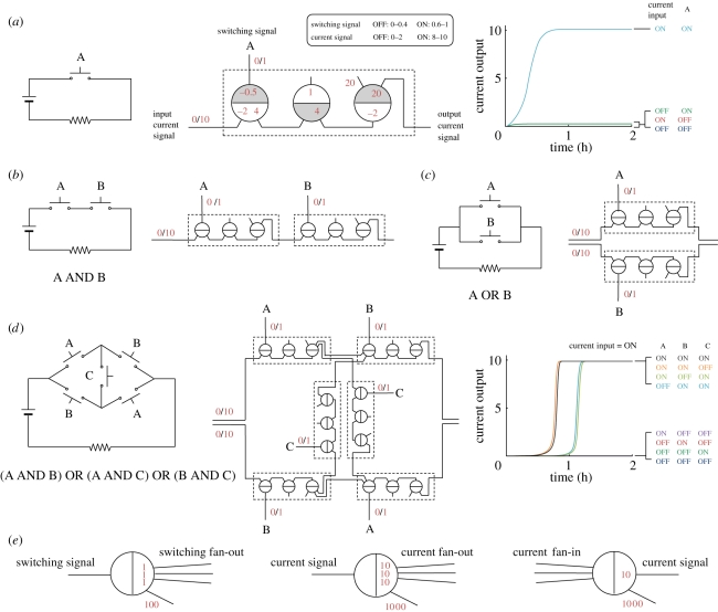
Figure 6.
Implementation of relay circuits. (a) A simple circuit with current source (battery) and controlled device (denoted by a resistor), the corresponding seesaw gate circuit, and its simulation using 1x = 50 nM. Shaded and unshaded sides of seesaw gates assist checking that a wire always connects different sides of two seesaw gates as required by node polarity, i.e. each wire connects the shaded side of one seesaw gate to the unshaded side of another. Switching signal A is provided at 1x if ON, or else 0.1x if OFF. Input current signal was provided at 10x; to verify that no output signal is produced when the current input is OFF, a 1x signal was provided. (b) AND logic. (c) OR logic. (d) A more complex circuit. Overlapping trajectories (orange and light blue) were shifted to the left by 100 s to make them visible. (e) Switching signal fan-out, current signal fan-out and current signal fan-in.

