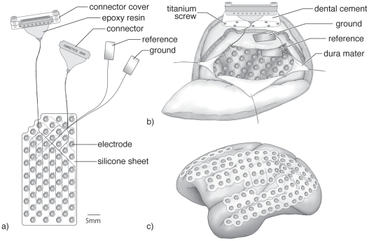
Figure 1. ECoG array, implantation and cortical coverage.
a) Sixty-four channel ECoG array with connectors and the reference and ground electrodes. b) Schematic figure showing how and where the ECoG array, reference electrode, ground electrode, and connectors were implanted c) Schematic view showing how the 128-channel ECoG electrode can cover the entire lateral cortical surface.

