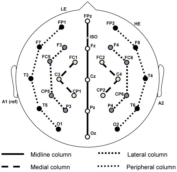
Figure 1. Electrode Montage.
Electrodes placed in the standard International 10–20 System locations included five sites along the midline (FPz, Fz, Cz, Pz, and Oz) and eight lateral sites, four over each hemisphere (F3/F4, C3/C4, T3/T4, and P3/P4). Eight additional 10–20 sites were altered to form a circle around the perimeter of the scalp. These altered sites included FP1′/FP2′ (33% of the distance along the circle between T3/T4), F7′/F8′ (67% of the distance between FPz and T3/T4), T5′/T6′ (33% of the distance between T3/T4 and Oz), and O1′/O2′ (67% of the distance between T3/T4 and Oz). In addition eight extended 10–20 system sites were also used (FC1/FC2, FC5/FC6, CP1/CP2, and CP5/CP6). The dotted lines represent the four columns used in analyses (i.e., midline, medial, lateral, peripheral). In the midline ANOVA, the electrode site factor had five levels (FPz, Pz, Cz, Pz, Oz); in the medial ANOVA, it had eight levels (FC1/FC2, C2/C4, CP1/CP2); in the lateral ANOVA, it had four levels of electrode site (F3/F4, FC5/FC6, CP5/CP6, P3/P4); in the peripheral ANOVA, it had five levels (FP1′/FP2′, F7′F8′, T3/T4, T5′/T6′, O1′/O2′).

