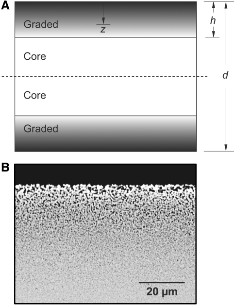
Figure 1.
Morphology of the graded zone. (a) Schematic of graded structure, defining coordinates. d and h are the thicknesses of plate and graded layer, respectively, and z is the distance from the free surface. (b) Section view of graded zone of glass-infiltrated Y-TZP, in back-scattered electron microscopy.

