
Figure 4.
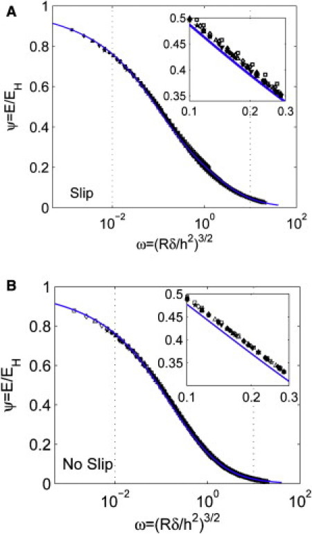
Numerical and analytical expression for the correction factor when R/h ≥ 2. (A) Slip interfacial condition and (B) no-slip interfacial condition between the indenter and the substrate. The solid line is given by Eq. 8 and the symbols indicate FEM results for different R/h values: 2 (□), 3(⋄), 4(▵), 5(▿), 6(☆), 7(●), 8(■), 9(♦), 10(▴), 11.5(▾), 12.7(★). The dotted lines indicate the typical range of ω in experiments. The insets show close-up views of the data points.