
Figure 1.
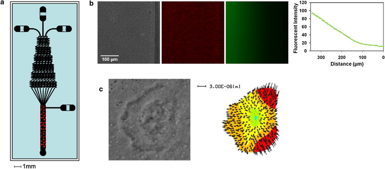
Overview of microfluidic traction force chamber. (a) A microfluidic gradient generator was used to create linear gradients over a traction force gel embedded in the main channel area of the device. Red dots represent the region where the traction force gels are placed and cells are observed. (b) Phase-contrast (left) and fluorescent-bead images (middle) of a traction force gel within the main channel of a microfluidic chamber, along with an image of fluorescein dye solution (right) flowing through the same region. At far right, an intensity plot of fluorescein fluorescence shows that a linear gradient is developed and maintained over the hydrogel. (c) Phase-contrast and traction-force microscopy map of a neutrophil oriented within the chamber in response to a chemical gradient.