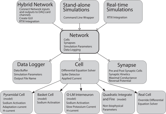
Figure 1.
General Network software design diagram. Boxes represent computer code class structures and arrows represent relationships between classes. Solid arrows represent object-oriented inheritance relationships and open arrows mean that an instance of the class pointed to is contained within the class the arrows originates from. Each class lists some representative class members (functions or variables) in small text. The Network class is at the core of the simulator. It contains the list of cells and synapses that define the network as well as data logging capabilities. The Cell class is a parent class to each individual cell type. It contains functions and variables common to all cells. Individual cells can be biophysical or non-biophysical if desired. The Network class is “wrapped” by three helper classes that allow the core of GenNet to be used in three different contexts. In one, GenNet is coupled to RTXI and physical hardware channel inputs are routed between model cells and real cells in an experimental preparation. In the other context, the simulator runs “stand-alone” in a purely virtual mode. In the last, GenNet is embedded within RTXI but used for real-time, single-cell simulations rather than hybrid network applications. All cells marked (model) are computer model versions of the cells they represent. The “real cell” is a placeholder class that serves to represent a living neuron within GenNet.

