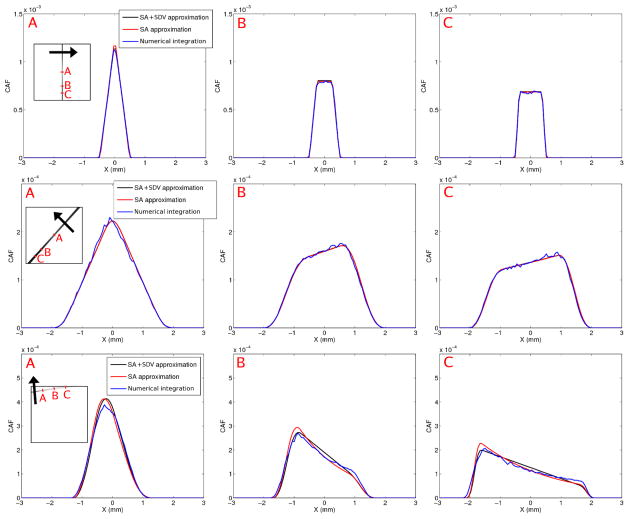
Figure 7.
CDRF for three LORs, shown along profiles taken perpendicular to the LOR axis, in the direction of the back arrow. Top row: Normal LOR connecting two 1 × 5 × 1 mm3 CZT detector voxels. The profiles through the CDRF at three locations (noted A, B and C in inset) are shown for three CDRF calculation methods: Numerical integration (NI), small-angle approximation (SA) and a combination of the SA and small detector voxel approximation (SA+SDV). Middle row: CDRF for a 45 deg oblique LOR going through the center of the FOV, with both detector voxels oriented vertically. Bottom row: CDRF for a very oblique LOR. The leftmost detector voxel, oriented horizontally, forms a 9 deg angle with the LOR while the rightmost detector voxel, oriented vertically, forms an 81 deg angle with the LOR.

