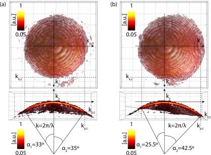
Fig. 4.
Experimental 3D CTF in different imaging conditions. The experimental CTF in (a) obtained for MO design imaging conditions (θ = 0°), whereas the CTF depicted in (b) is obtained for non-design conditions (θ = 15°), according to Fig. 2. The upper row shows the top view on the CTF and bottom row shows the side view through the CTF for kx = 0, respectively. Colorbars.

