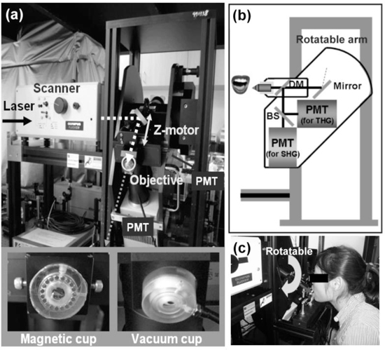
Fig. 1.

In vivo harmonic generation biopsy system. (a) Photograph of the optical virtual biopsy system. The illumination source was a Cr:forsterite laser. The collimated laser beam performed a 2D scan by a pair of fast galvanometer mirrors and PMT (photomultiplier tube) recorded the harmonic signals. A z-motor changed the tissue stabilizer (magnetic cup and vacuum cup) position along the light propagation axis so that the relative position between the objective and the tissue surface can be controlled. (b, c) A schematic diagram and a photograph of the rotatable system. SHG and THG signals were divided by a beamsplitter and guided into two PMTs. The objective of the imaging system was fixed on a rotatable arm to adapt the volunteer’s oral cavity.
