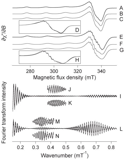
Figure 2.
Analysis of the X-band EPR spectra of 63Cu(II)–PrPf2 components 2 and 3. Trace A is the X-band EPR spectrum of component 2, and traces B and C are simulations of A that differ only in the number of coordinated nitrogen atoms, either two (B) or three (C). The g⊥ regions of the two simulations B and C are shown overlaid in inset D. Trace E is the X-band EPR spectrum of component 3, and traces F and G are simulations of E that differ only in the number of coordinated nitrogen atoms, either three (F) or four (G). The g⊥ regions of the two simulations F and G are shown overlaid in inset H. Trace I shows overlaid Fourier transforms of A, B, and C. Inset J shows the intensity-adjusted Fourier transforms of A (the experimental spectrum of component 2; thick line) and B (the simulation assuming two coordinated nitrogens; thin line) over the region 0.4–0.5 mT−1. Inset K shows the intensity-adjusted Fourier transforms of A (the experimental spectrum of component 2; thick line) and C (the simulation assuming three coordinated nitrogens; thin line) over the region 0.4–0.5 mT−1. Trace L shows overlaid Fourier transforms of E, F, and G. Inset M shows the intensity-adjusted Fourier transforms of E (the experimental spectrum of component 3; thick line) and F (the simulation assuming three coordinated nitrogens; thin line) over the region 0.3–0.4 mT−1. Inset N shows the intensity-adjusted Fourier transforms of E (the experimental spectrum of component 3; thick line) and G (the simulation assuming four coordinated nitrogens; thin line) over the region 0.3–0.4 mT−1.

