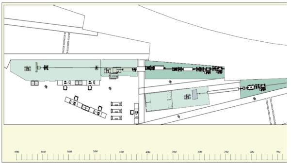
Figure 2.
Layout of canted undulator beamlines on NSLS-II experimental floor. The x-ray beam propagates from right to left, and thus the long downstream experimental station appears at far left, the shorter experimental station just upstream of it. Just below the canted undulator beamlines is a neighboring beamline that would view a bending magnet or three-pole wiggler

