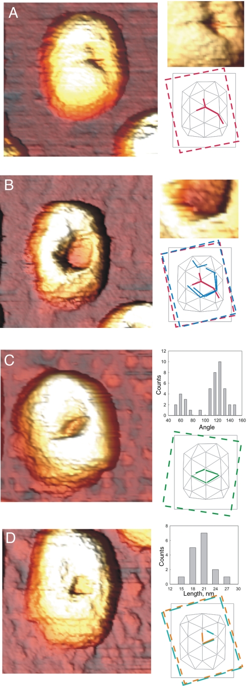
Fig. 4.
Fracture patterns. (A) Fracture lines on prohead shells: (Upper Inset) enlarged feature; (Lower Inset) location of fracture on the surface lattice. (B) Same prohead as in A imaged in a further scan. The fractures have propagated to the complete displacement of a hexameric plate: (Upper Inset) enlargement of feature; (Lower Inset) lattice location of fracture. (C) Displaced triangles on another prohead: (Upper Inset) histogram of orientations of fracture lines with respect to the long axis of the prohead; (Lower Inset) lattice location of fracture. (D) Displaced triangle: (Upper Inset) histogram of the lengths of fracture lines with clearly visible ends (N = 16); (Lower Inset) lattice location of fracture. Insets in A and B are 3D rendered with a different light source position. Dashed colored frames indicate the first visual guesses (under different illumination angles of the 3D-rendered images) of the orientation of the long axis of the shells, which was then refined by matching the fracture lines into the shell lattice.

