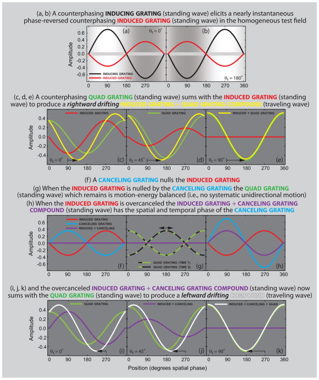
Figure 1.
Explanation of the quadrature-phase motion cancelation technique. (a, b) The background illustrates the appearance of a grating induction stimulus for inducing gratings at 0° and 180° temporal phase. A counterphasing inducing grating (standing wave illustrated by black line) elicits a nearly instantaneous phase reversed counterphasing induced grating (standing wave illustrated by red line) in the homogeneous test field. (c–e) A counterphasing quadrature grating (standing wave illustrated by green line) added to the test field sums with the induced grating (red line) to produce a rightward drifting induced-plus-quadrature grating compound (traveling wave illustrated by yellow line). (f) A canceling grating (blue line) added to the test field in the same temporal phase as the induced grating (red line) but in 180° spatial phase is used to null the induced grating (purple line). (g) When the induced grating is nulled by the canceling grating the quad grating which remains is motion-energy balanced and causes no systematic unidirectional motion. (h) When the induced grating is over-canceled the induced grating plus canceling grating compound (standing wave illustrated by purple line) has the spatial and temporal phase of the canceling grating (blue line). (i–k) The over-canceled induced-plus-canceling grating compound sums with the quadrature grating to produce a leftward drifting compound (traveling wave illustrated by white line).

