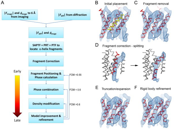
Figure 1. The fragment-based phase extension method for electron crystallography.
(A) Flowchart of the fragment-based phase extension procedures. (B–F) Fragment positioning procedures prior to phase calculation. The example shown here is for the AQP4 test case. (B) The 20-residue α-helix fragments were initially located by the SAPTF+PRF+PTF algorithm using the experimental amplitude and phase data to 6Å resolution. One helix (yellow) was incorrectly placed outside the density. (C) The fragment outside the density was manually removed. (D) During fragment correction, the fragment that was placed into the kinked density was split into two shorter fragments. (E) Fragments were further corrected by shortening fragments that were too long or elongating fragments that were too short to match the visible density. (F) The fragment positions were refined as rigid bodies against the diffraction amplitude data to correctly position the fragments in the asymmetric unit. Following rigid body refinement all fragments were well positioned and used for the initial phase calculation.

