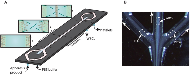
Figure 1. Acoustophoresis chip design.
A) Schematic diagram of the acoustophoresis chip. Apheresis sample enters the channel from the side channels. Wash buffer enters the chip from the central inlet. The transducer generates an acoustic standing wave between the channel walls and the suspended cells are moved by the acoustic force into the pressure node located in the centre of the channel. As the acoustic force on a cell is size dependent, the larger leukocytes experience a higher radiation force than the smaller platelets. B) Microscope image of the separation process taken at the trifurcation. The larger leukocytes (WBC) have been centered in the channel by the ultrasonic standing wave and are collected in the central outlet, while the smaller platelets (PLT) are less acoustically affected and exit through the side branches. A movie of the platelet separation process is provided in the supplementary material.

