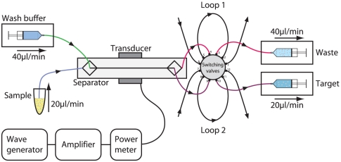
Figure 6. Schematic diagram of the acoustophoresis set up.
Two pumps connected to the chip outlets and set in withdrawal mode, and one pump connected to the chip central inlet, infusing wash buffer were responsible for flow control. The PBPC sample was connected to the chip side inlet and entered into the separation channel at a net flow rate set by the three pumps. A switching valve injector was inserted between the chip outlets and the outlet syringe pumps enabling the collection of outlet samples. The ultrasonic standing wave was generated by a piezoelectric transducer operated via an amplifier by a waveform generator setting the resonance frequency to 2 MHz.

