
Fig. 1.
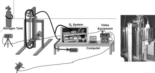
A schematic of the setup with a treadmill and oxygen analysis system. O2 system indicates the oxygen analysis electronics. Air was drawn through the metabolic chamber, out the top past the subject's head, and into the oxygen analysis system. The oxygen analysis equipment fed data into the laptop computer. During the trial the four channels are displayed on the laptop screen while data are being recorded. M indicates the variable speed motor used to run the treadmill, and C1 and C2 indicate the video cameras. Video equipment consisted of, from top to bottom, a video mixer, a VCR, and a TV. Video data were fed into the mixer such that the two views were displayed side by side on the TV. Data from the mixer were fed into the VCR, and then from the VCR into the TV to ensure the image on the TV was the exact same as that being recorded. Photo shows a L. tardigradus climbing in the metabolic chamber.