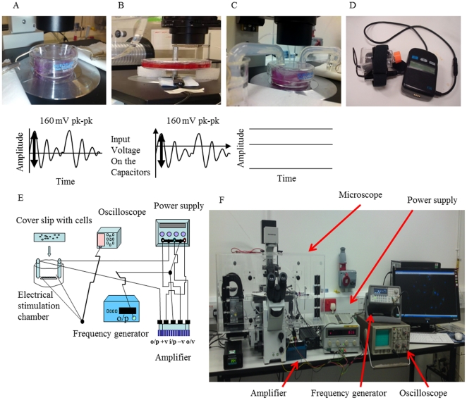
Figure 8. Setup for electrical stimulation used in this study.
A, Electrical stimulation (ES) chamber used for Degenerate Wave and the Degenerate waveform. B, ES apparatus for Capacitive Coupling (CC) and the CC waveform. C, ES apparatus for Direct Current (Direct Current) and DC Waveform. D, Pulsed Electromagnetic field stimulation (PEMF) device. E, Schematic diagram of the ES apparatus used for DC, CC and DW. F, Photograph of the microscope incubator where the ES stimulation takes place for CC, DW and CC and where control cells are placed.

