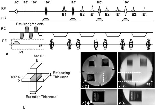
Figure 1.
(a) Targeted-DW-SPLICE pulse sequence diagram, (b) IVI scheme. To avoid non-CPMG artifacts, the spin echoes (solid lines) and stimulated echoes (dash lines) were separated by doubling the readout gradient durations. Odd (E1) and even (E2) echoes were formed alternatively into spin and stimulated echoes. Magnitude images were reconstructed using E1 and E2 datasets respectively; these were subsequently averaged to form the final image. The slice-selective gradient for the 90o excitation pulse is applied along the PE direction, while the slice-selective gradient for the180o refocusing pulses are applied along the slice-selective direction to provide a limited FOV along the PE direction. Signal formation is limited to the overlapping region between the two selective excitation pulses (gray region in b). (c) Images of the resolution phantom acquired using full FOV single-shot DW-SE-EPI (c(1)) and full FOV DW-SPLICE (c(2)) sequences; reduced FOV images covering the resolution markers within the lower left quadrant of the phantom (dash boxes in c(1) and c(2)) acquired using targeted-DW-SE-EPI (c(3)) and targeted-DW-SPLICE (c(4)). Less image distortion (arrow in c(1)) was observed in targeted-DW-SE-EPI image. The targeted-DW-SPLICE sequence effectively reduced blurring in the PE direction compared to full-FOV DW-SPLICE.

