Abstract
Non-Cartesian imaging provides many advantages in terms of flexibility, functionality, and speed. However, a major drawback to these imaging methods is off-resonance distortion artifacts. These artifacts manifest as blurring in spiral imaging. Common techniques that remove the off-resonance field inhomogeneity distortion effects are not sufficient, because the high order concomitant gradient fields are nontrivial for common imaging conditions, such as imaging 5 cm off isocenter in an 1.5T scanner. Previous correction algorithms are either slow or do not take into account the known effects of concomitant gradient fields along with the field inhomogeneities. To ease the correction, the distortion effects are modeled as a non-stationary convolution problem. In this work, two fast and accurate post-gridding algorithms are presented and analyzed. These methods account for both the concomitant field effects and the field inhomogeneities. One algorithm operates in the frequency domain and the other in the spatial domain. To take advantage of their speed and accuracy, the algorithms are applied to a real-time cardiac study and a high-resolution cardiac study. Both of the presented algorithms provide for a practical solution to the off-resonance problem in spiral imaging.
Keywords: concomitant gradient field, field inhomogeneity, spiral, non-stationary convolution
Introduction
High-resolution magnetic resonance imaging (MRI) is based on the resonance properties of molecules at a particular frequency. However, as recognized and studied previously, off-resonance effects are inevitable given the nature of the imaging technology (1). The effects result in phase errors manifesting as different artifacts depending on the imaging strategy. In spiral imaging, the artifacts are seen as geometric distortion and blurring. The exact cause of the off-resonance effects includes main B0 field inhomogeneity, tissue-induced susceptibility, chemical shifts, and eddy currents. Another cause, which will be the focus of this study, is the concomitant gradient fields. The off-resonance from this effect is unavoidable because according to Maxwell’s equations, the uniform gradients used in imaging are always accompanied by higher order terms. These extra terms are proportional to the gradients applied and inversely proportional to the main field strength (2). This off-resonance distortion becomes more severe in modern high-performance systems with gradient amplitudes of ≥ 40 mT/m and slew rates of ≥ 150 T/m/s (3–6).
In non-Cartesian scans, the distortion effects are not straightforward to correct, and intelligent schemes must be designed to alleviate the problem. To use the advantages of non-Cartesian scans, such as speed and efficiency of the spiral trajectory, this image degradation must be addressed. Strategies implemented to reduce the off-resonance effects cover different aspects of the MR imaging process: pulse sequence and reconstruction. On the pulse sequence side, solutions include altering the gradient design (3,6) and pulsing the main magnetic fields (7). However, in typical MRI scans where speed is important, these schemes are not plausible. Therefore, we focus our correction efforts in the reconstruction process. Algorithms previously developed to correct for field inhomogeneity can be used to correct for the concomitant gradient fields. The correction scheme can be applied to different aspects of the image reconstruction: the time-dependent signal (8,9), the gridded data in the frequency space (10–13), and the Fourier-transformed data in image space (14–17).
Failing to correct for both field inhomogeneities and concomitant gradient fields may result in insufficient correction or even in an increase in blurring (4,18,19). A recent study for non-Cartesian scans demonstrated an effective correction scheme that corrects for both effects using a Chebyshev approximation on gridded data (18). The correction was performed using a “semi-automatic” algorithm where the off-resonance errors were reduced by minimizing the phase of the final image (13, 20, 21).
We propose a non-iterative approach using a simple quadratic approximation. We reduce the computational complexity to correct for both inhomogeneity and concomitant off-resonance effects in real-time. We examine solutions for scans with spiral trajectories where the off-resonance artifacts manifest as blurring (4, 22), or more specifically, as a non-stationary convolution. One advantageous property is that the spiral trajectory yields smoothly varying off-resonance kernels that aid us in our post-gridding algorithms. Our proposed approaches use the special property of the spiral trajectory to simplify the model and to greatly accelerate the correction process. Two fast and simple field inhomogeneity algorithms are modified and used to correct the field inhomogeneity and concomitant field distortion: a multi-frequency interpolation algorithm applied in the frequency domain (10) and a non-stationary deconvolution algorithm applied in the image domain (15–17).
The area of interest for our study is the heart. The size and position of the heart and vessels make off-resonance from both concomitant gradient fields and field inhomogeneities unavoidable. Furthermore, for cardiac applications such as monitoring interventional procedures or diagnosing the rapid and irregular motion of arrhythmia, being able to image the anatomy rapidly in real-time is necessary for quality exams. Additionally, a very fast data acquisition rate is required to reduce artifacts from the constant cardiac motion and blood flow. To avoid any delay in the imaging for real-time cardiac applications, the speed of the reconstruction process must keep up with the fast acquisition rate. Thus, we propose to effectively correct the distortion effects with an emphasis on speed.
The concomitant fields can be calculated directly from the applied readout gradients. This effect is first examined and modeled in a way to ease our correction schemes. Next, the field inhomogeneity measured through a low resolution field map is incorporated into the algorithm to yield a more accurate correction. Lastly, the multi-frequency interpolation algorithm and the non-stationary deconvolution algorithm are applied and compared in a real-time cardiac study and a high-resolution cardiac study.
Theory
The concomitant gradient field effects are first examined. Using special properties of the spiral trajectory, the distortion problem is simplified and shown as a non-stationary convolution. Afterward, we incorporate the effects of the field inhomogeneities.
Concomitant Gradient Field
For most MR techniques, only the linear terms of the net magnetic field amplitude B are used for an elegant Fourier analysis. However, the higher-order concomitant terms become significant for more demanding scans with low B0 fields, high linear gradient fields, or large distances from the isocenter. For example, a spiral scan at 5 cm off isocenter starts exhibiting notable blurring in a 1.5 T scanner.
By examining Maxwell’s equations, the expression for B is derived using Taylor series expansion (3). From this equation of B, the concomitant gradient field is approximated to the second order as
| [1] |
Variable G = (Gx, Gy, Gz) is the time-dependent linear gradient field. Variable X = (X, Y, Z) is the spatial coordinate in the magnet. The terms are negligible given a main magnetic field of B0 ≥ 1.0 T. For spiral scans, the expression for Bc can be simplified further using approximations specific to the spiral gradients (4):
| [2] |
where
| [3] |
| [4] |
| [5] |
The value of the through-plane gradient gz is 0 for two-dimensional imaging. Function Fn depends on the elements in the rotation matrix: a = (a1, a2, …, a9). Equations for Fn, derived by King et al (4), are presented in more detail in the Appendix as Eq. [A.2]. With Eq. [2], the gradient dependency is decoupled from the spatial dependency to allow for more sophisticated correction algorithms. For convenience, the remainder of our discussion will be in terms of the logical image coordinates x and the respective gradients g rather than the actual scanner coordinates X and the actual applied gradients G.
The concomitant gradient field results in an additional phase accrual, Φc, on the acquired signal:
| [6] |
The resulting signal equation can be written as
| [7] |
where
| [8] |
Using the expression for Bc defined in Eq. [2], Φc can be re-written as
| [9] |
where
| [10] |
Function Ca(x) is based on all other parameters of Eq. [2] that are not included in h(t), such as the scan location and rotation. The actual equation is defined in the Appendix as Eq. [A.1]. For ease of calculation and implementation, h(t) can be mapped to k-space yielding h(k) for a generalized function of Φc:
| [11] |
The change of variable from t to k depends on the assumption that every value of k maps to a unique value of t. Additionally, since h(k) is smoothly varying in space for spiral trajectories, the function can be further simplified through polynomial fitting.
The image can be reconstructed by mapping the signal s(t) to k-space as M(k) and taking an inverse Fourier transform resulting in image I(x). To simplify our analysis, we ignore discretization effects and perform our calculations in the continuous domain. The uncorrected image with concomitant distortion Ic (x) can be obtained by manipulating the signal equation described by Eq. [7]:
| [12a] |
| [12b] |
| [12c] |
| [12d] |
| [12e] |
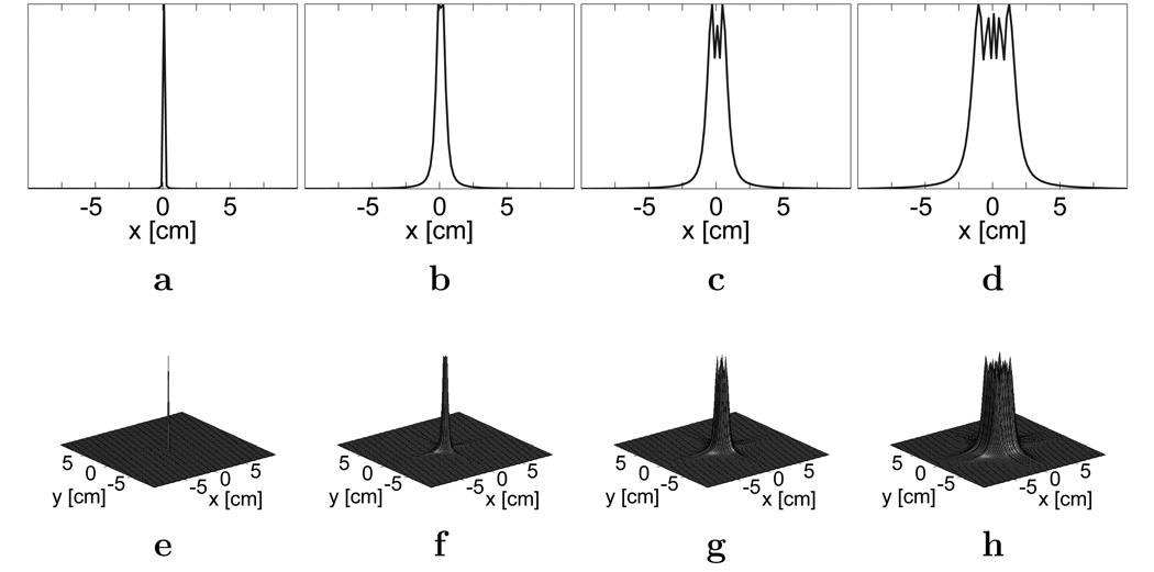
The resulting expression in Eq. [12e] models the distortion as a non-stationary convolution kernel f(x′, x). Examples of these kernels are described in Fig. 1. The correction problem can then be solved using signal processing schemes, such as using wavelets and filter banks, that were developed for working with a non-stationary kernel.
FIG. 1.
Magnitude plots of example off-resonance convolution kernels in the image domain for a resolution of 1.88 × 1.88 mm2. a,e: At 1 Hz. b,f: At 50 Hz. c,g: At 100 Hz. d,h: At 200 Hz. Plots in (a), (b), (c), and (d) have y = 0.
An important characteristic of the concomitant distortion kernel is that this non-stationary kernel is relatively narrow and varies slowly in space. Therefore, we can approximate the problem with a series of stationary convolution kernels, where one kernel is used for a localized area of interest. This kernel can be applied in either the k-space domain or in the image-space domain.
Field Inhomogeneity Effects
Concomitant gradient fields are known theoretical effects that can be calculated. Unfortunately, in practice, other off-resonance effects are present in distorting scans. The factors that contribute to the additional image degradation include main field inhomogeneities, subject dependent susceptibility variations, and gradient induced eddy currents. In off-isocenter scans that induce concomitant gradient field distortion, field inhomogeneities play a significant role in reducing scan quality. Neglecting concomitant effects, the off-resonance effects Δω(x) can be described by the following equation:
| [13] |
Unlike the concomitant gradient effects, the Δω(x) needs to be measured through field map acquisitions. Many different techniques can be used for the field map acquisition, such as comparing the phase of images at two different echo times (23, 24) or estimating the map through “automatic” algorithms applied to the acquired data (13, 20, 25).
Using any of the common approaches to measure the field inhomogeneity, the acquired field map Δω(x) includes most of the phase distortion contributing to the image degradation. This includes, to a certain extent, tissue-susceptibility and eddy currents. However, these methods do not accurately measure the concomitant gradient fields. By comparing the phase of images at two different echo times, the phase from the concomitant gradient field is completely removed, because the data acquired at each echo time is affected by the same concomitant gradient field. For the case of estimating the map through “automatic” algorithms, the concomitant gradient field is naturally included in the estimate. Unfortunately, strong concomitant gradient fields will reduce the accuracy of this field map estimate and will increase the computational complexity for calculating the map (18).
For our purpose of rapid reconstruction, the two echo time approach is used to measure the field map Δω(x). The concomitant gradient fields are not included in the map, thus, emphasizing the need for a combined correction. From examining the signal equations described by Eqs. [7] and [13], these spatially-dependent phase effects can be easily combined and corrected simultaneously with the concomitant gradient effects.
Methods
Field-map based off-resonance methods have been developed for fast correction. Two of these approaches are modified to remove the concomitant distortion effects while emphasizing speed.
To remove the distortion effects from the image, we apply a conjugate phase correction. Using the distortion model described in Eq. [12e], the distorted image Ic can be corrected by deconvolving the off-resonance kernels using localized stationary kernels κ(x′, x):
| [14] |
In terms of an appropriate selection for κ(x′, x), we choose a kernel that satisfies the following property for a constant x′:
| [15] |
The kernel we use is defined as
| [16] |
A simple proof that Eq. [16] satisfies Eq. [15] is shown in the Appendix.
Frequency Domain
The distortion correction can be performed in the frequency domain. In this approach, a series of images are generated by deconvolving the entire image by κ(x′, x) for different values of x′. The final reconstructed image is a linear combination of the demodulated images. Using κ(x′, x) defined in Eq. [16], this algorithm can be described mathematically as
| [17] |
The values of xj are chosen such that different areas in the image are corrected. The values of the weights wj (x) can be determined using a multi-frequency interpolation method (10).
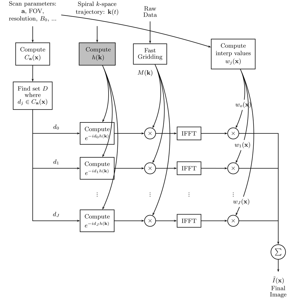
The decomposition of Φc(k, x) into Ca(x) and h(k) in Eq. [11] is used to simplify the implementation of this approach. A finite set D of values is formed to uniformly cover possible values of Ca(x). Values are selected to be between the minimum and maximum of Ca(x) for a particular image. Using the notation that dj is the jth element of D, the multi-frequency approach can be summarized as
| [18] |
Here, the correction kernel κ mentioned in Eq. [16] is approximated by . The minimum number of elements in set D (or the number of frequency bins b) can be calculated from the following expression which is modified from Man et al (10):
| [19] |
A diagram of the multi-frequency interpolation method is shown in Fig. 3.
FIG. 3.
Diagram for the multi-frequency interpolation method. The box in light gray can be precomputed before scanning. If the scan parameters are not changed, the values for exp [−djh(k)] and wj(x) can also be precomputed. Eq. [18] corresponds to the operations in this figure.
Image Domain
Another approach in correcting for the phase distortion is to apply the correction in the image domain. In this scheme, a series of correction kernels can be calculated from the concomitant field gradient equations. These kernels are convolved with the image in image space to effectively remove the phase error.
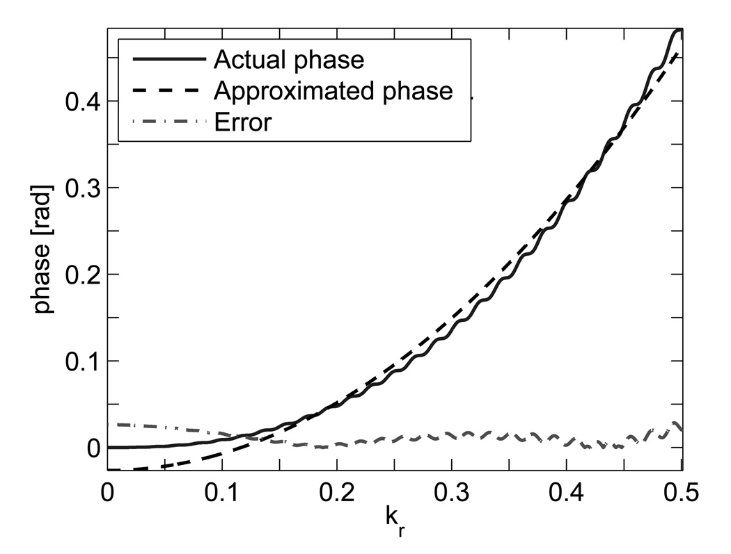
As proposed by Ahunbay and Pipe in a generalized deblurring technique for spiral scans, the correction time can be reduced with a small sacrifice in accuracy through a separable quadratic phase model (15). By analyzing the concomitant gradient fields for spiral trajectories (Fig. 2), we model these effects as
| [20] |
FIG. 2.
Concomitant gradient field phase at X = (−18.0, 15.0, 40.0) mm plotted in normalized k-space for a sagittal scan. The k-space trajectory is normalized to extend from −0.5 to 0.5. The phase is plotted with respect to kr, the magnitude of k.
Here, function Φc of Eq. [11] is simplified by approximating h(k) with a quadratic function: . In concordance with h(t) in Eq. [10], constants p1 and p2 are based on the value of ∫ g2(τ)dτ for the corresponding k. These constants can be estimated using least-squares fitting.
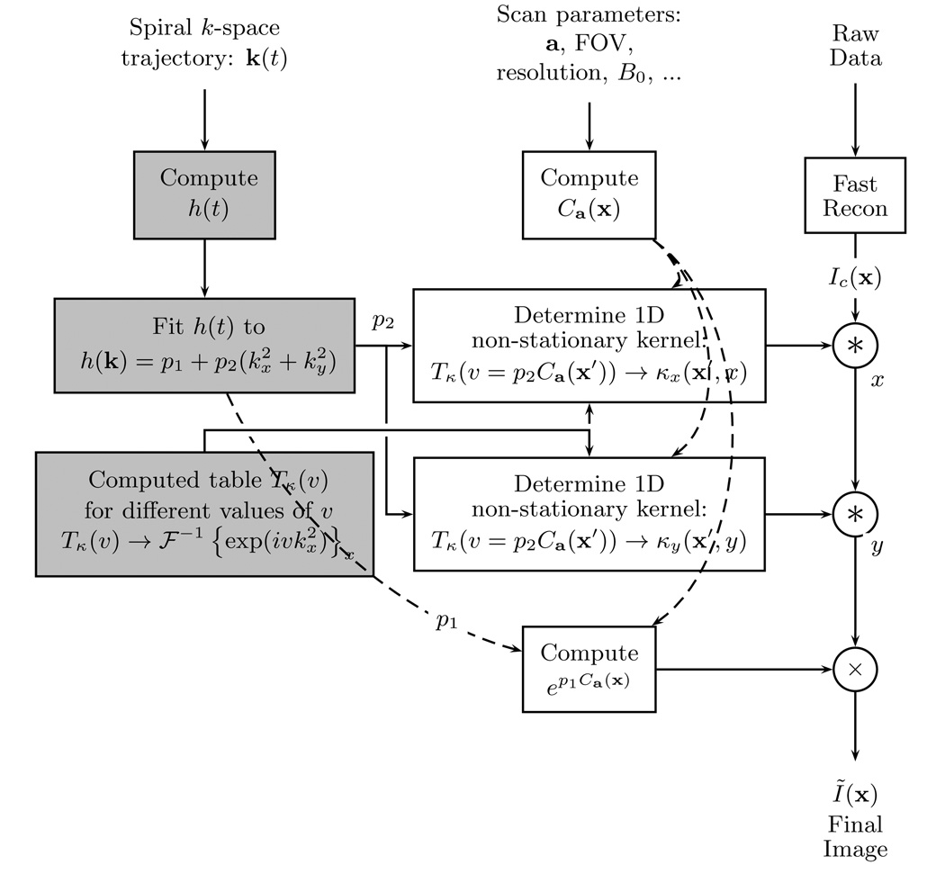
With this separable quadratic phase model, the distorted image can be corrected with a one-dimensional convolution kernel κx for a given x′ and a:
| [21] |
For this approach, the correction kernel κ(x′, x) from Eq. [16] is re-defined as κ(x′, x) = κx(x′, x)κy(x′, y) with κx(x′, x) = κy(x′, y) for a square image. See Fig. 4 for a summary of this method.
FIG. 4.
Diagram for the image convolution method. The boxes in light gray can be precomputed before scanning. The non-stationary convolution (*) is a one dimensional operation.
Field Inhomogeneity Effects
The off-resonance effects based on the field map Δω(x) can also be fit to a separable quadratic phase model. A simple way to do this is by approximating t of Eq. [13] as a quadratic function of k (15): . The value of constant pt can be estimated using least-squares fitting. The one-dimensional kernel based on the field map for a given x′ can then be approximated as
| [22] |
Combining both effects as seen individually in Eqs. [21] and [22], we arrive at an expression for the total off-resonance phase:
| [23] |
and the correction kernel:
| [24] |
In regard to a practical implementation of the image-domain method, the correction kernels can be easily precomputed and stored in a look-up table by ignoring the term p1Ca(x′)/2 and varying the total value of ptΔω(x′) + p2Ca(x′). The value of p1Ca(x′)/2 can be incorporated later when computing the convolutions in image space. The following set of equations describe the look-up table Tκ (υ) for non-integer index υ:
| [25] |
| [26] |
For an index v, Tκ(v) yields an array of values that describe the one-dimensional kernel. Because Tκ(v) holds a discrete set of entries, v(x) must be rounded to the nearest discrete v entry. In short, the correction kernel for location x′ can be found with the following entry look-up: Tκ(v(x′)) → κx(x′, x).
Additionally, the off-resonance phase measured by the field map can be simultaneously corrected with the concomitant phase in a multi-frequency interpolation approach. Using the total off-resonance phase approximated in Eq. [23], we can redefine the general equation of Φc in Eq. [11] with the following substitutions:
| [27] |
| [28] |
Similar to the image-domain convolution method, the extra constant phase factor, p1Ca(x), can be applied separately to the image. With the described substitutions, the extra phase can be easily corrected using the multi-frequency interpolation method as described by Eq. [18]. For this algorithm, a different model can be used in place of the separable quadratic h(k). To still achieve simultaneous correction, both phase-error sources must be represented by a common model of h(k).
Experiment
The two algorithms, multi-frequency and image convolution, were implemented in C++ and incorporated as reconstruction modules in the RTHawk real-time MR system (HeartVista, Inc., Los Altos, CA). These modules have the capability to independently correct for the off-resonance measured by a field map, to independently correct for the off-resonance calculated through the concomitant field equation, and to simultaneously correct for both off-resonance errors. The speed and flexibility of the developed algorithms were exploited in the RTHawk real-time environment.
Experiments were performed on an 1.5 GE Signa EXCITE scanner. The off-resonance field map Δω(x) was measured by acquiring two images with an echo-time difference of 4.60 ms to ensure a sufficient dynamic range when deriving the map. A single-shot spiral trajectory was used to acquire the low-resolution (6.5 × 6.5 mm2) field map. Using an 8-channel cardiac coil, all images were obtained using a TE/TR of 3.84/23.68 ms and a spectral-spatial excitation with a slice thickness of 5 mm. Real-time images were acquired using a 4-interleave spiral trajectory with a FOV of 20 cm and a resolution of 1.88 × 1.88 mm2. For the high-resolution studies, a 16-interleave spiral trajectory was used to acquire two sets of images: one with a FOV of 20 cm and a resolution of 0.72 × 0.72 mm2, and another with a FOV of 24 cm and a resolution of 0.86 × 0.86 mm2. In all experiments, data from each coil was gridded and corrected separately before the final image was composed by a sum-of-squares. If a more sophisticated coil-combination algorithm is used, it is possible to perform the correction on a single final image. This can be done if the phase information is preserved such as in a non-accelerated sensitivity-encoded reconstruction (26,27). Note that the coil-sensitivity phase does not affect the quality of the correction due to its slowly-varying nature. The reconstruction was performed on a dual core AMD Opteron 270 4 × 2 GHz processor with 7 GB RAM. We examine only one of the coils when analyzing the speed of our algorithms.
For the multi-frequency interpolation algorithm, the images were demodulated at 10 different frequencies before combining using interpolation coefficients wj (x) estimated using DFT approximations of a non-integer shifted sample (10). The number of frequency bins b was determined to satisfy Eq. [19]. For some experiments, a smaller value for b could have been used, but this value was fixed for consistency. For example, if the image was modulated by a single frequency component, as in the case of the concomitant gradient field distortion in an axial scan, only one frequency bin was required. This special case can be confirmed by examining the concomitant gradient field equation described in Eq. [1]. In an axial scan where Gz = 0, the distortion only depends on the Gx and Gy gradients applied and the location of the slice in Z. Thus, each image pixel has the same off-resonance phase, and this effect can be described by one frequency bin. For the image-domain approach, a table Tκ(v) of 1000 kernels was pre-computed in the range of 0 to 200 Hz of off-resonance distortion. This phase range was tuned to encompass different degrees of distortion seen in our experiments, and the size of the table was determined to adequately describe the changes in the distortion. Each convolution kernel had a total width of 20 pixels.
Results
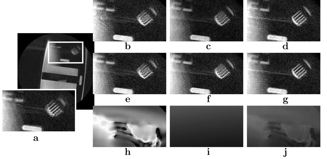
A high-resolution phantom study was performed to test the correction algorithms. This experiment was a practical approach in verifying the algorithms without the concern of motion blurring, chemical shifts, and other unforeseen artifacts from in vivo scans. The results of the experiment are shown in Fig. 5 where sagittal slices of a resolution phantom were acquired at X = (−25.1, 8.44, 35.9) mm. The field inhomogeneity correction and the concomitant gradient field correction demonstrated deblurring at different parts of the image. The areas of correction can be pinpointed by analyzing the phase error maps of each effect. Consistent with theory, the field inhomogeneity was most prevalent at material boundaries and the concomitant gradient field was most prevalent furthest from isocenter. Additionally, the combined correction revealed a cleaner image than with correcting for only one of the off-resonance effects.
FIG. 5.
Phantom study comparing the off-resonance effects and the algorithms used. Sagittal slices of a resolution phantom were acquired at X = (−25.1, 8.44, 35.9) mm with a FOV of 20 cm and a resolution of 0.72 × 0.72 mm2. a: Original image. b–d: Corrected using the multi-frequency interpolation algorithm. e–g: Corrected using the image-domain convolution algorithm. h–j: Phase error modelled by off-resonance maps with the same window/level. Images in (b), (e), and (h) correspond to correcting with only the field map. Images in (c), (f), and (i) correspond to correcting only the concomitant gradient field. Images in (d), (g), and (j) correspond to correcting both effects.
The multi-frequency interpolation method and the image convolution method results were almost indistinguishable; the same areas of each image were corrected. Because of the trivial differences between the results, we concluded that either algorithm can be used. Thus, for other experiments, we used results from only one algorithm - specifically, the image-domain convolution algorithm.
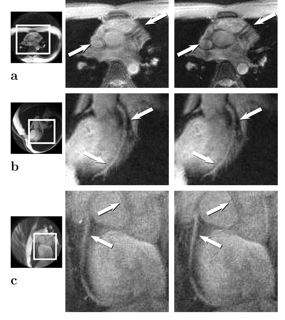
To show robustness, in vivo studies were performed. In a high-resolution cardiac study shown in Fig. 6, the atrial wall and the coronary arteries were examined. An axial slice and an oblique slice were obtained at different locations to emphasize the coronary arteries. Using the correction algorithm, a recovery of the resolution was seen at the high-frequency artery walls. In Fig. 6a and Fig. 6c, the image was acquired at a substantial distance from isocenter (> 10cm), so the issue of gradient non-linearity had to be addressed. Applying the correction in the presence of gradient non-linearity is described in more detail in the Discussion.
FIG. 6.
Triggered high resolution study using the image convolution method. The original images are shown in the middle, and the corrected images are shown in the right column. a: Axial slice at X = (22.2,−26.8, 105.5) mm imaging the left coronary artery. b: Oblique slice at X = (9.7,−33.2, 73.7) mm imaging the left anterior descending artery. c: Oblique slice at X = (−12.5,−37.4, 99.3) mm imaging the right coronary artery. The images in (a) and (b) are acquired with a FOV of 24 cm and a resolution of 0.86 × 0.86 mm2. The image in (c) is acquired with a FOV of 20 cm and a resolution of 0.72 × 0.72 mm2. Note the sharpness in the atrial walls and coronary arteries.
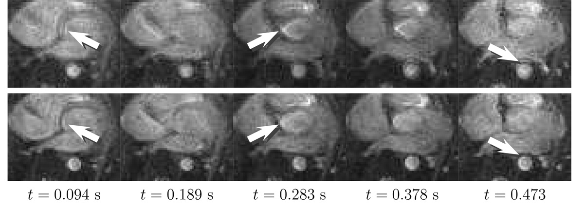
The high-resolution study confirmed the quality of the correction, and a low-resolution real-time cardiac study was used to confirm the speed of the algorithms. In Fig. 7, sequential axial slices from a real-time study are shown. The improved quality of the real-time series can be seen by taking note of the cardiac walls and the aorta boundaries. A short computation time was extremely beneficial in maintaining a reasonable frame rate. The images were acquired at a rate of ~ 10 frames per second (FPS), or 40 FPS when using a more intelligent reconstruction scheme such as incorporating a sliding window or a Kalman filter (28). With the unoptimized C++ implementation, each algorithm yielded an average computation time of ~ 0.1 s for a 106 × 106 size image, manifesting as a small delay in the system. For frame rates higher than 10 FPS, the implementation must be better optimized for speed. Strategies to reduce delay can be incorporated, including increasing the computing resources to parallelize the processing of each frame, correcting only the region of interest, or applying the correction when the desired anatomy is found.
FIG. 7.
Sequential axial slices from a real-time cardiac study corrected using the image convolution method. The deblurring is noticeable in the aorta and atrial walls with some residual blurring partially due to motion. The 5 mm slices were obtained at X = (17.2,−0.8,−50.0) mm. The top row is the original image series, and the bottom row is the corrected image series using both the field map and the concomitant gradient fields.
Discussion
As seen in the results, the spatial resolution lost due to the concomitant gradient fields can be recovered through the proposed correction algorithms. Some of the residual phase errors can be corrected by incorporating the field inhomogeneity information. However, the proposed methods require a fairly accurate field map when incorporating the field inhomogeneity correction. Therefore, care must be taken when using the acquired field map. Some approaches to minimize field map error include thresholding for noise, fitting the field map to a polynomial model, or correcting the field map iteratively. Overall, there is a trade-off between accuracy and speed. In our approaches, we focus on speed while maintaining reasonable accuracy.
Gradient Non-linearity
In the discussion of off-resonance, gradient non-linearity becomes an issue in affecting the scan quality through image shading and spatial distortion (29,30). These image artifacts can be observed in Fig. 5. For most cases, the gradient non-linearity does not affect the proposed algorithms noticeable due to the trivial amount of gradient distortion. However, for substantial gradient non-linearity, as exhibited by spatial warping reportedly measured up to 25 mm in pixel translation for a FOV of 24 cm (31), the demodulation kernel becomes significantly altered.
The gradient non-linearity can be defined with the following expression:
| [29] |
Here, gxa is the actual non-linear x-gradient, gx is the ideal linear x-gradient, and Δgx(x) is the spatially-dependent non-linearity. To correct for Δgx(x), the most common scheme is to model the problem in terms of spatial warping. In the MR signal equation, the gradient is multiplied by the spatial coordinate as gxx. Using Eq. [29] for a more accurate x-gradient expression, we rewrite this product in terms of a spatially-warped image space:
| [30a] |
| [30b] |
The gradient non-linearity is corrected by simply correcting for the spatial warping described by xw. Unfortunately, for the concomitant gradient field terms that include higher-order terms and cross-terms, the gradient non-linearity cannot be simply mapped to a warped image-space.
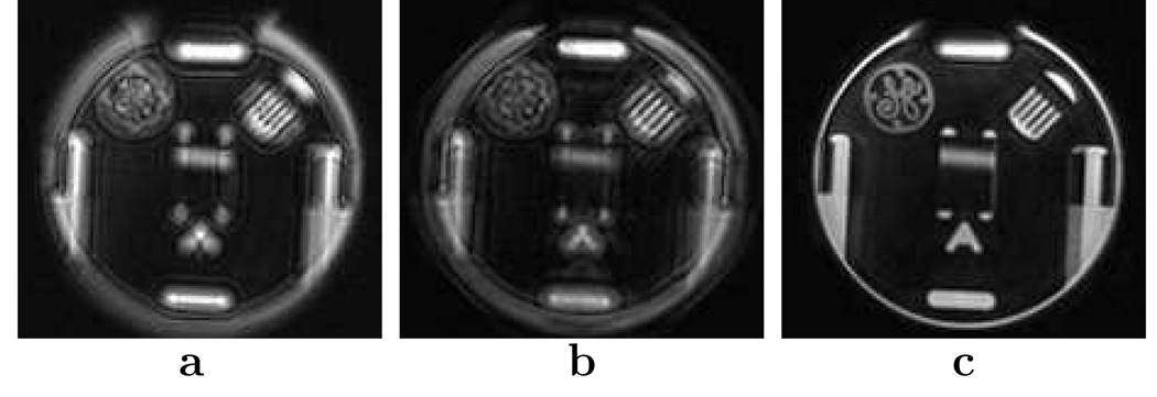
To incorporate gradient non-linearity distortion, extra steps are applied to the correction schemes. First, a portion of the non-linearity is corrected by spatially unwarping the distorted image. This step shapes the image such that the image coordinate x at each pixel is readily determined and accurate. Next, the off-resonance correction is performed with a phase-scaled kernel. We approximate the gradients as linear across the image-space width of the demodulation kernel. This estimate is fairly reasonable since the gradient non-linearity is smoothly and slowly varying across normal scan field of views. Assuming uniform gradient non-linearity in the image plane axes (Δgx(x) ≈ Δgy (x)), the non-linearity effect is incorporated by scaling the phase Φc by a factor of (1 + Δgx(x))2. The scaling factor is derived from Eqs. [2], [6], and [29]. These modifications are added to our correction schemes, and the result is shown in Fig. 8. In this experiment, the phantom was positioned far from isocenter to accentuate the gradient non-linearity. We see that the concomitant gradient field correction fails when the gradient non-linearity is not taken into account. For most of the results given, the scans exhibited a trivial amount of gradient non-linearity. In these cases, addressing the non-linearity did not noticeably improve the correction. However, for Figs. 6a and 6c, the gradient non-linearity had to be incorporated to ensure quality corrections.
FIG. 8.
Effect of gradient non-linearity on the off-resonance correction. a: Original image. b: Corrected image without using gradient non-linearity information. c: Corrected image with gradient non-linearity information. The axial slice was acquired at X = (5.3,−1.1, 120.0) mm with a FOV of 24 cm and a resolution of 0.86 × 0.86 mm2. The image was cropped to magnify the region of interest. The concomitant gradient field and the field map phase was corrected in (b) and (c) using the image convolution method.
Unfortunately, the assumption that Δgx(x) ≈ Δgy(x) does not hold for non-axial scans, because the Z-gradient coil has different properties compared to the X-gradient and Y-gradient coils. As a result, the correction kernel may no longer be radially symmetric. The gradient non-linearity becomes difficult to incorporate in the multi-frequency interpolation algorithm. The efficiency of this algorithm depends on the assumption that multiple areas of the image can be corrected using one demodulation kernel. In non-axial scans, a unique demodulation kernel at each pixel location may be required due to the location-based gradient non-linearity. In these situations, the algorithm becomes impractical to implement. Fortunately, this problem can be easily mitigated in the image-domain convolution algorithm by applying two different kernels for each x location: a x-direction kernel phase-scaled by (1 + Δgx(x))2 and a y-direction kernel phase-scaled by (1 + Δgy(x))2. In certain oblique scans, the kernel may no longer be readily separable. However, we approximate the gradient non-linearity to have separate x-direction and separate y-direction effects. With this simplification, residual blurring remains, but it does not greatly affect quality of the correction.
Further investigation can be done to improve the image convolution correction scheme in the presence of gradient non-linearity. Additionally, further work can be done to simultaneously correct for the phase distortion along with the gradient non-linearity.
Method Comparison
Assuming that the off-resonance maps are already obtained, the total computation complexity for the multi-frequency interpolation algorithm can be roughly summarized as
| [31a] |
| [31b] |
The first term, tmn2, is the number of multiplications required to apply the demodulation phase of one frequency bin to the gridded k-space data. The second term, tFFT, is the time needed to compute the Fourier transform of the demodulated image of size n × n. The last term, (tm+ta)n2, is the number of operations required to add the derived images as a linear combination. Variables tm and ta correspond to the time to compute complex multiplication and complex addition. Assuming that the look-up tables have no computation cost, the total computation complexity for the image-domain convolution algorithm can be roughly summarized as
| [32a] |
| [32b] |
The first term, tFFT, is the time used to transform the gridded data to the image domain. The last term, 2l(tm + ta) × n2, is the total time to apply the one-dimensional convolution kernels (in both x and y) at each pixel. These kernels have a total pixel width of l.
From Eq. [31b], we see that the computation time for the multi-frequency interpolation algorithm is dominated by the computation of the Fourier transforms. The number of bins b can be reduced to decrease the computation time. From Eq. [32b], we see that the computation time for the image convolution algorithm is dominated by the convolution operation. The computation time can be reduced by narrowing the width l of the kernel. As mentioned previously, the computation time for both algorithms were very similar with l = 20 and b = 10. A more in depth analysis of the trade-offs of modifying these variables can be performed, but given the results and the emphasis of speed, the values used were sufficient.
In terms of accuracy, the two different approaches cannot be fairly compared, because each makes different approximations. The multi-frequency interpolation approximates the problem by interpolating through different off-resonance frequencies; whereas the image convolution correction approximates the phase error through a separable kernel model. Using the same demodulation kernel for both approaches, it is hypothesized that the image convolution approach results in a more accurate image because of its ability to use a more accurate kernel at each location. However, given the nature of the slowly-varying off-resonance phase, the difference in the correction approaches are difficult to observe.
In terms of practical implementation, the image convolution correction is recommended over the frequency-domain approach for the following two reasons. First, for high-varying phase errors, the multi-frequency interpolation requires more and more frequency bins (Eq. [19]). This increases the computation time of the multi-frequency interpolation method. For the image-domain approach, the number of kernels can be increased to account for a wide range of phase variation, and the computation time will not be affected. Secondly, the image convolution method can better cater its correction to localized effects without any significant penalty. For example, different x and y image-domain kernels could be used to incorporate the gradient non-linearity effects in the correction. In the frequency-domain method, the calculations may become too unwieldy when considering gradient non-linearity. However, the multi-frequency interpolation method does have an advantage over the image convolution method in that it has better efficiency for cases with slowly-varying phase errors. An example of this case is when the phase error can be corrected by only one frequency bin.
Gradient Alterations and Other Scan Sequences
As mentioned in the analysis, the concomitant gradient field depends on the gradient waveforms applied. Therefore, any alterations in the gradient waveform, such as a gradient amplitude alterations or scan geometry modifications, change the prescribed correction kernel. This is also an issue if the main field inhomogeneity map is used to alter the sequence during the scan, such as adding a center frequency off-set or adding an additional gradient component. For minor alterations, the correction scheme is not affected noticeably. Because incorporating this correction using the field map comes at little extra cost, it is recommended to not alter the sequence significantly, and correct the field inhomogeneity simultaneously using the proposed algorithms.
The algorithms can potentially be extended to other non-Cartesian trajectories as long as the gradient dependency of the concomitant gradient field can be decoupled from its spatial dependency. This decoupling for the spiral trajectory can be seen in Eq. [2], and the decoupling is modeled in Eq. [11] as h(k) and Ca(x). Additionally, if h(t) cannot be successfully mapped to h(k), more work must be done to allow the image convolution method to be a reasonable method in terms of computational complexity. From the results of our correction scheme, this area of research is worthwhile to pursue in improving non-Cartesian scan quality.
In all our experiments, a traditional gradient-echo sequence was used to acquire the images. Because the algorithms correct for the errors caused by the gradients applied and the scan location, they can be directly applied to other common cardiac sequences such as steady-state free precession (SSFP) imaging. For SSFP imaging, the readout length is innately short resulting in smaller phase accrual from the concomitant gradient fields and the field inhomogeneities. In this case, blurring may be insignificant and correction could all together be avoided.
As noted, the algorithms can correct images using more sophisticated parallel imaging techniques. Some of these multi-coil techniques, such as the iterative self-consistent parallel imaging reconstruction method (32), can correct for off-resonance effects. Using our formulation, the concomitant gradient field distortion can be easily incorporated into such methods for a more accurate correction. However, for cardiac applications where speed is emphasized, the computation intensity of these techniques do not allow for true real-time imaging. Our approach is favored for these cases.
Conclusion
Correction for both field inhomogeneities and concomitant gradient fields results in significant improvement in image quality. The concomitant gradient field information can be easily added to existing off-resonance algorithms with little extra cost. The two approaches presented here, multi-frequency interpolation and non-stationary image-domain convolution, are fast enough for real-time applications and accurate enough for high-resolution scans. Results from phantom and cardiac studies are reported with noticeable improvements.
Acknowledgments
This work was supported by NIH training fellowship, GE Medical Systems.
A Appendix
A.1 Concomitant gradient field equation
To simplify our notations, we combine the rotation and location dependency of the concomitant gradient field into one equation. This equation is denoted as Ca(x) and is defined as
| [A.1] |
Eq. [A.1] greatly simplifies the concomitant gradient field effects by decoupling the gradient and location dependency as seen in the function Φc in Eq. [9]. The values of F1, F2, … F6 were defined by King et al (4). The equations are reproduced here for convenience:
| [A.2a] |
| [A.2b] |
| [A.2c] |
| [A.2d] |
| [A.2e] |
| [A.2f] |
| [A.2g] |
A.2 Non-stationary kernel
Based on Eq. [12e], a formula for f(x′, x) is derived as
| [A.3a] |
| [A.3b] |
Since Φc is symmetrical about the origin, we can remove the minus sign in the transform and rewrite the equation as
| [A.4] |
Using the following equation for κ(x′, x):
| [A.5] |
we can show that this equation is sufficient to remove the blurring effects for a fixed location x′:
| [A.6a] |
| [A.6b] |
| [A.6c] |
The convolution kernel κ can accurately remove the phase distortion effects given an accurate measurement of the phase error. To reiterate, we are also relying on the assumption that f(x′, x) changes very slowly with respect to x′.
References
- 1.O’Donnell M, Edelstein WA. NMR imaging in the presence of magnetic field inhomogeneities and gradient field nonlinearities. Medical Physics. 1985;12:20–26. doi: 10.1118/1.595732. [DOI] [PubMed] [Google Scholar]
- 2.Norris DG, Hutchison JM. Concomitant magnetic field gradients and their effects on imaging at low magnetic field strengths. Magnetic Resonance Imaging. 1990;8:33–37. doi: 10.1016/0730-725x(90)90209-k. [DOI] [PubMed] [Google Scholar]
- 3.Bernstein MA, Zhou XJ, Polzin JA, King KF, Ganin A, Pelc NJ, Glover GH. Concomitant gradient terms in phase contrast MR: analysis and correction. Magnetic Resonance in Medicine. 1998;39:300–308. doi: 10.1002/mrm.1910390218. [DOI] [PubMed] [Google Scholar]
- 4.King KF, Ganin A, Zhou XJ, Bernstein MA. Concomitant gradient field effects in spiral scans. Magnetic Resonance in Medicine. 1999;41:103–112. doi: 10.1002/(sici)1522-2594(199901)41:1<103::aid-mrm15>3.0.co;2-m. [DOI] [PubMed] [Google Scholar]
- 5.Du YP, Zhou XJ, Bernstein MA. Correction of concomitant magnetic field-induced image artifacts in nonaxial echo-planar imaging. Magnetic Resonance in Medicine. 2002;48:509–515. doi: 10.1002/mrm.10249. [DOI] [PubMed] [Google Scholar]
- 6.Zhou XJ, Tan SG, Bernstein MA. Artifacts induced by concomitant magnetic field in fast spin-echo imaging. Magnetic Resonance in Medicine. 1998;40:582–591. doi: 10.1002/mrm.1910400411. [DOI] [PubMed] [Google Scholar]
- 7.Meriles CA, Sakellariou D, Trabesinger AH, Demas V, Pines A. Zero- to low-field MRI with averaging of concomitant gradient fields. Proceedings of the National Academy of Sciences. 2005;102:1840–1842. doi: 10.1073/pnas.0409115102. [DOI] [PMC free article] [PubMed] [Google Scholar]
- 8.Noll DC, Meyer CH, Pauly JM, Nishimura DG, Macovski A. A homogeneity correction method for magnetic resonance imaging with time-varying gradients. IEEE Transactions on Medical Imaging. 1991;10:629–637. doi: 10.1109/42.108599. [DOI] [PubMed] [Google Scholar]
- 9.Sutton BP, Noll DC, Fessler JA. Fast, iterative image reconstruction for MRI in the presence of field inhomogeneities. IEEE Transactions on Medical Imaging. 2003;22:178–188. doi: 10.1109/tmi.2002.808360. [DOI] [PubMed] [Google Scholar]
- 10.Man LC, Pauly JM, Macovski A. Multifrequency interpolation for fast off-resonance correction. Magnetic Resonance in Medicine. 1997;37:785–792. doi: 10.1002/mrm.1910370523. [DOI] [PubMed] [Google Scholar]
- 11.Schomberg H. Off-resonance correction of MR images. IEEE Transactions on Medical Imaging. 1999;18:481–495. doi: 10.1109/42.781014. [DOI] [PubMed] [Google Scholar]
- 12.Moriguchi H, Dale BM, Lewin JS, Duerk JL. Block regional off-resonance correction (BRORC): A fast and effective deblurring method for spiral imaging. Magnetic Resonance in Medicine. 2003;50:643–648. doi: 10.1002/mrm.10570. [DOI] [PubMed] [Google Scholar]
- 13.Chen W, Meyer CH. Semiautomatic off-resonance correction in spiral imaging. Magnetic Resonance in Medicine. 2008;59:1212–1219. doi: 10.1002/mrm.21599. [DOI] [PubMed] [Google Scholar]
- 14.Kadah YM, Hu X. Simulated phase evolution rewinding (SPHERE): a technique for reducing B0 inhomogeneity effects in MR images. Magnetic Resonance in Medicine. 1997;38:615–627. doi: 10.1002/mrm.1910380416. [DOI] [PubMed] [Google Scholar]
- 15.Ahunbay E, Pipe JG. Rapid method for deblurring spiral MR images. Magnetic Resonance in Medicine. 2000;44:491–494. doi: 10.1002/1522-2594(200009)44:3<491::aid-mrm22>3.0.co;2-z. [DOI] [PubMed] [Google Scholar]
- 16.Cheng JY, Santos JM, Pauly JM. Fast concomitant gradient field correction for spiral imaging. Proceedings of the 17th Annual Meeting of ISMRM; April 2009; Honolulu, Hawaii, USA. p. 2844. [Google Scholar]
- 17.Devaraj A, Bhavsar P, Pipe JG. Rapid concomitant field correction for 2D spiral imaging. Proceedings of the ISMRM & ESMRMB Joint Annual Meeting; May 2010; Stockholm, Sweden. p. 3104. [Google Scholar]
- 18.Chen W, Sica CT, Meyer CH. Fast conjugate phase image reconstruction based on a Chebyshev approximation to correct for B0 field inhomogeneity and concomitant gradients. Magnetic Resonance in Medicine. 2008;60:1104–1111. doi: 10.1002/mrm.21703. [DOI] [PMC free article] [PubMed] [Google Scholar]
- 19.Cheng JY, Santos JM, Pauly JM. Fast field inhomogeneity and concomitant gradient field correction for spiral cardiac imaging. Proceedings of the ISMRM & ESMRMB Joint Annual Meeting; May 2010; Stockholm, Sweden. p. 3108. [Google Scholar]
- 20.Man LC, Pauly JM, Macovski A. Improved automatic off-resonance correction without a field map in spiral imaging. Magnetic Resonance in Medicine. 1997;37:906–913. doi: 10.1002/mrm.1910370616. [DOI] [PubMed] [Google Scholar]
- 21.Noll DC, Pauly JM, Meyer CH, Nishimura DG, Macovski A. Deblurring for non-2D Fourier transform magnetic resonance imaging. Magnetic Resonance in Medicine. 1992;25:319–333. doi: 10.1002/mrm.1910250210. [DOI] [PubMed] [Google Scholar]
- 22.Yudilevich E, Stark H. Spiral sampling in magnetic resonance imaging - the effect of inhomogeneities. IEEE Transactions on Medical Imaging. 1987;6:337–345. doi: 10.1109/TMI.1987.4307852. [DOI] [PubMed] [Google Scholar]
- 23.Webb P, Macovski A. Rapid, fully automated, arbitrary-volume in vivo shimming. Magnetic Resonance in Medicine. 1991;20:113–122. doi: 10.1002/mrm.1910200112. [DOI] [PubMed] [Google Scholar]
- 24.Schneider E, Glover G. Rapid in vivo proton shimming. Magnetic Resonance in Medicine. 1991;18:335–347. doi: 10.1002/mrm.1910180208. [DOI] [PubMed] [Google Scholar]
- 25.Chen W, Meyer CH. Fast automatic linear off-resonance correction method for spiral imaging. Magnetic Resonance in Medicine. 2006;56:457–462. doi: 10.1002/mrm.20973. [DOI] [PubMed] [Google Scholar]
- 26.Roemer PB, Edelstein WA, Hayes CE, Souza SP, Mueller OM. The NMR phased array. Magnetic Resonance in Medicine. 1990;16:192–225. doi: 10.1002/mrm.1910160203. [DOI] [PubMed] [Google Scholar]
- 27.Bydder M, Larkman DJ, Hajnal JV. Combination of signals from array coils using image-based estimation of coil sensitivity profiles. Magnetic Resonance in Medicine. 2002;47:539–548. doi: 10.1002/mrm.10092. [DOI] [PubMed] [Google Scholar]
- 28.Sumbul U, Santos JM, Pauly JM. A practical acceleration algorithm for real-time imaging. IEEE Trans Med Imaging. 2009;28:2042–2051. doi: 10.1109/TMI.2009.2030474. [DOI] [PMC free article] [PubMed] [Google Scholar]
- 29.Wang D, Doddrell DM. A proposed scheme for comprehensive characterization of the measured geometric distortion in magnetic resonance imaging using a three-dimensional phantom. Medical Physics. 2004;31:2212–2218. doi: 10.1118/1.1767051. [DOI] [PubMed] [Google Scholar]
- 30.Baldwin LN, Wachowicz K, Thomas SD, Rivest R, Fallone BG. Characterization, prediction, and correction of geometric distortion in 3 T MR images. Medical Physics. 2007;34:388–399. doi: 10.1118/1.2402331. [DOI] [PubMed] [Google Scholar]
- 31.Wang D, Strugnell W, Cowin G, Doddrell DM, Slaughter R. Geometric distortion in clinical MRI systems Part I: evaluation using a 3D phantom. Magnetic Resonance Imaging. 2004;22:1211–1221. doi: 10.1016/j.mri.2004.08.012. [DOI] [PubMed] [Google Scholar]
- 32.Lustig M, Pauly JM. SPIRiT: Iterative self-consistent parallel imaging reconstruction from arbitrary k-space. Magnetic Resonance in Medicine. 2010;64:457–471. doi: 10.1002/mrm.22428. [DOI] [PMC free article] [PubMed] [Google Scholar]


