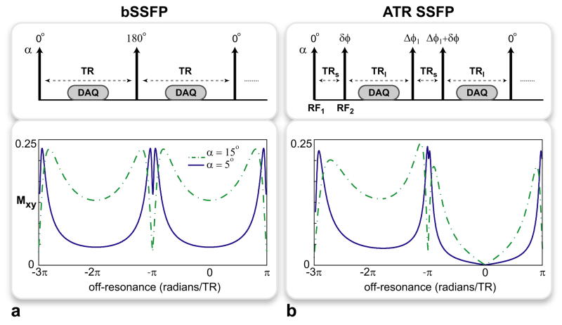
Figure 1.
The pulse sequence diagrams and the corresponding transverse magnetization profiles for the a: bSSFP and b: ATR SSFP sequences. All RF pulses have the same tip angle, α, and the labels on top of the arrows denote the individual RF phases. The profiles were simulated for α = {5°, 15°} and T1/T2 = 5, assuming TR = TRs + TRl for ATR SSFP. While the off-resonant peaks created around -π radians are similar for both sequences, ATR SSFP achieves superior on-resonant suppression at all tip angles. For bSSFP (a), there is considerable remnant on-resonant signal even with α = 5°. On the contrary, ATR SSFP yields near-zero signal regardless of α as seen in b.

