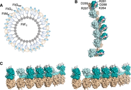
Figure 6.
Structural model for the upper part of the C-ring. (A) Overall plan of FliG and FliM organizations. The arrangement is similar to that proposed by Brown et al (2007), with adjustments to reflect more-current information on FliG structure. FliM is light brown and FliG is cyan. (B) More detailed view of a section of the rotor. Colouring is as in (A), but with the three parts of FliG (FliGNM, linking helix and FliGC) coloured with increasing intensity, and the active-site ridge shown in atom colours to highlight the conserved charged residues that interact with the stator (Zhou et al, 1998a). The dashed line indicates the hypothesized path of the stator (relative to the rotor) as the motor turns (see the text). (C) Stereo-view (crossed-eye) of a section of the rotor. The view is in a roughly radial direction (out-to-in). The active-site ridge on FliGC is coloured white.

