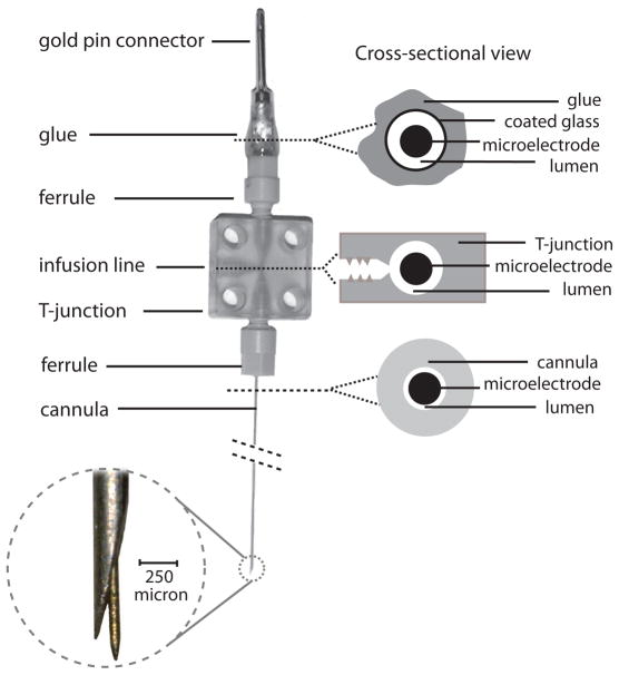
Figure 1.
Schematic of the microinjectrode. A thin microelectrode is passed through a 32G cannula (OD: 236 μm). The cannula is connected to a T-junction via a ferrule. The electrode is passed through a T-junction and a polyimide-coated glass tube and its end is soldered to a gold pin. The polyimide tubing, gold pin, and ferrule are all glued together. Thus unscrewing the ferrule retracts the microelectrode tip back into the cannula. On right, cross-sections through different parts of microinjectrode are shown. Top cross-section is a cut above the top ferrule. The lumen in this section is only open to the T-junction since its top part is sealed by glue. The middle cross-section is through the T-junction. Polyimide tubing connects to the opening of T-junction by a ferrule. Bottom cross-section is through the cannula. Enlarged view of the microelectrode and cannula tips shows their relative position and size.

