Abstract
Recent developments in cardiac catheter technology promise to allow physicians to perform most cardiac interventions without stopping the heart or opening the chest. However, current cardiac devices, including newly developed catheter robots, are unable to accurately track and interact with the fast moving cardiac tissue without applying potentially damaging forces. This paper examines the challenges of implementing force control on a flexible robotic catheter. In particular, catheter friction and backlash must be compensated when controlling tissue interaction forces. Force controller designs are introduced and evaluated experimentally in a number of configurations. The controllers are based on the inner position loop force control approach where the position trajectory is adjusted to achieve a desired force on the target. Friction and backlash compensation improved force tracking up to 86% with residual RMS errors of 0.11 N while following a prerecorded cardiac tissue trajectory with accelerations of up to 3800 mm/s2. This performance provides sufficient accuracy to enable a wide range of beating heart surgical procedures.
I. Introduction
Innovations in cardiac catheter technology allow an increasing number of cardiac procedures to be performed without large incisions and while the heart is beating. These procedures include both electrophysiology (e.g. tissue ablation) and interventional cardiology (e.g. heart valve replacement) [1]. These advances, however, use catheters that are manually positioned at speeds well below beating heart tissue motion. This approach necessitates the use of complaint catheter tips or specialized end-of-catheter devices that avoid the need for dexterous interaction with the intracardiac tissue. In general, currently available catheter systems lack the speed and dexterity to safely interact with and repair fast moving cardiac tissue.
Cardiac catheters are long and thin flexible tubes that are inserted into the vascular system and passed into the heart. Current robotic cardiac catheters, such as the commercially available Artisan Control Catheter (Hansen Medical, Mountain View CA, USA) or CorPath Vascular Robotic System (Corindus Vascular Robotics, Natick MA, USA), permit a human operator to control the positioning of a catheter in the lateral direction and advance it through the vasculatures [2]–[4]. However, these systems do not provide sufficient speeds to compensate for the motion of the heart. Fast motion compensation is required for many beating heart procedures to enable dexterous interaction and prevent the catheter from colliding with the cardiac structures [5].
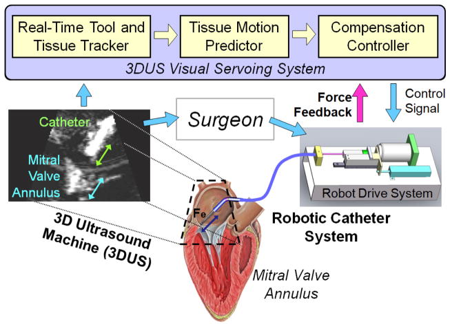
In previous work, we demonstrated that fast cardiac motion compensation is possible with a robotic catheter [6],[7]. The catheter system, shown in Fig. 1, consists of a 3D ultrasound (3DUS) visual servoing system, a drive system, and the actuated catheter. The goal of the previous work was to identify the position servoing performance limitations in the catheter system and define methods to improve the system’s motion tracking ability. The goal of the present work is to enable the catheter to apply a constant force on the moving tissue while performing a repair task on the beating heart. An example clinical application that requires force control is inserting surgical anchors for a mitral valve annuloplasty procedure [5],[8]. To achieve this goal, force control methods designed specifically for actuated catheter systems are proposed and evaluated.
Fig. 1.
The robotic system servos the catheter inside the heart with a control system that utilizes 3DUS information and force feedback. The surgeon then manipulates the catheter to perform the repair.
A. Force Control Characteristics
Robotic systems that have linearizable system models and slow relative motion with the environment can often achieve good performance with simple force control schemes based on force error feedback [9]. Robotic manipulators with significant nonlinear system dynamics, such as friction, backlash, or internal compliance, or devices that interact with fast-moving environments usually require more sophisticated control algorithms [10]–[12]. One example is the use of inner position control loops and outer force control loops to implement force control on industrial manipulators to address the friction in the joints and transmission systems [13]. Another example is the use of feedforward velocity and acceleration terms to maintain a force on fast moving cardiac structures with a rigid handheld actuated tool, as presented in our previous work [14].
The force control task presented here is limited by the high friction and deadzone backlash characteristics of the robotic catheter system as well as the fast motion of the cardiac structures [6], [14]. This paper proposes and evaluates conventional and novel control systems to enable the robotic catheter system to apply a constant force to moving target tissue. First, the catheter system and tip force sensor designs are presented in detail. Then the force control schemes are derived and evaluated on the catheter hardware with a motion simulator target. Finally, the results are analyzed to better understand which system parameters are crucial for ensuring accurate and stable force control.
II. System Design
A. Robotic Catheter System
The robotic catheter system is designed to interact with the outer annulus of the mitral valve, located between the left atrium and ventricle. The system design parameters were selected from human mitral valve physiology values [15]. The principal functional requirements are a single actuated linear degree of freedom with at least 20 mm of travel that can provide a maximum velocity and acceleration of at least 210 mm/s and 3800 mm/s2, respectively. These values have been shown to be sufficient to compensate for the human mitral annulus motion [15]. The system should also be able to apply a sufficient force to modify cardiac tissue, approximately 4 N.
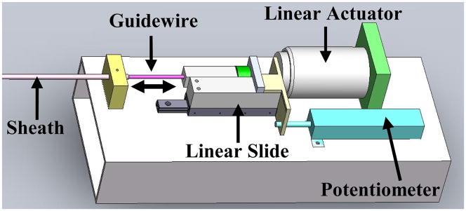
The complete system is composed of three main modules: the drive system that actuates the catheter, the catheter module that is inserted through the vasculature into the heart, and the 3D ultrasound visual servoing system that tracks the tissue and commands the catheter to follow the motion (Fig. 1). The drive system, shown in Fig. 2, includes a linear voice coil actuator with 50.8 mm of travel and a peak force of 26.7 N (NCC20-18-02-1X, H2W Technologies Inc, Valencia CA, USA), a linear ball bearing slide (BX3-3, Tusk Direct, Inc., Bethel CT, USA), and a linear potentiometer position sensor (CLP13, P3 America Inc., San Diego, CA, USA). The catheter module (Fig. 3) is composed of a 70 cm long nylon sheath with a 2.70 mm inner diameter and an uncoated stainless steel coil guidewire with a 2.39 mm outer diameter. The unactuated catheter sheath can be manually flexed as required by the vascular geometry (bent, twisted, etc.) while the guidewire is servoed inside the sheath by the drive system. A more complete description of the catheter system is provided in [6].
Fig. 2.
The robot drive system located at the base of the catheter.
Fig. 3.
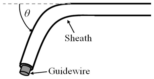
Catheter configuration parameters. The bend angle, θ, was varied to evaluate the force control methods.
Custom C++ code is used to control the system and make measurements via a data acquisition card at 1 kHz. Commands to the linear actuator are amplified by a linear current amplifier (AMPAQ, Quanser Inc., Markham, Ontario, Canada). For clinical implementation, the target position will be tracked using a 3D ultrasound imaging system that streams 3D images of the interior of the heart at video frame rates (28–30 fps) [7].
B. 3D Printed Force Sensor
The catheter tip force sensor was created with the design specifications of less than 5.5 mm outer diameter, less than 1 mm deflection under maximum load of 10 N, RMS errors less than 0.2 N, and good immunity to lateral forces. The package must accommodate an electromagnetic (EM) tracking sensor and allow for good integration with the robotic catheter.
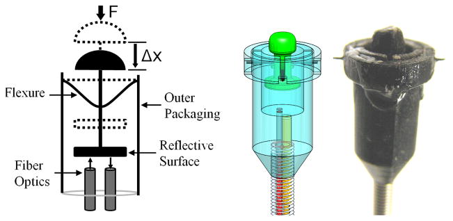
Fig. 4 presents the catheter force sensor design that achieves these specifications. The structure of the force sensor was fabricated using 3D printing (Objet Connex500 3D Printer, Objet Geometries Ltd, Billerica, MA, USA). Nitinol wire flexures (0.25 mm diameter) were selected and arranged in a perpendicular configuration (Fig. 4). A fiber optic displacement sensor was selected to measure the displacement of the reflective surface supported by the flexures. The sensor operates by converting the displacement of the flexures into a force value using a nonlinear calibration [16]. One advantage of the fiber optic sensor is that it does not require current-carrying wires within the heart.
Fig. 4.
Diagram, solid model, and photograph of the 3D printed force sensor at the tip of the catheter stem.
An electromagnetic (EM) tracker was integrated into the catheter tip to provide position information (3D Guidance trakSTAR, Model 90 sensor, 0.9 mm diameter, Ascension Technology Corp. Burlington VT, USA). This EM tracker has a submillimeter spatial resolution but over 20 ms of latency that limit its use for accurate and stable close-looped control.
III. Control Method
The controller goal is to apply a desired force on a fast moving target with the robotic catheter system. A standard error-based force control law is
| (1) |
where Fa is the actuator force, Fd is the desired force, Fe is the force applied to the environment, Kf and Kv are controller gains, and ẋ is the robot velocity [9]. However, this control approach will not work for the robotic catheter system because of the limitations identified in [6], including backlash and friction in the catheter transmission system [12],[17]. These limitations prevent the force regulator in (1) from correctly responding to the force tracking error in a stable manner because the internal dynamics of the catheter obstruct the controller action from being accurately transmitted to the catheter tip. For example, as the target changes directions, the backlash in the catheter prevents the forces applied by the catheter from immediately changing. Therefore, there is a larger force tracking error that produces an even larger response from the force regulator. This often results in instability or the system entering a limit cycle [17].
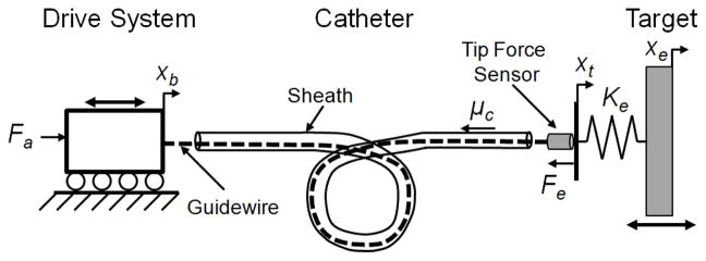
To overcome these issues, we propose a method that uses the force error term to modulate the commanded position trajectory of the catheter. This approach is similar to the inner position loop force control approaches used to implement force control on high-friction industrial manipulators [13]. Fig. 5 presents a diagram of the catheter system experimental setup and the system model variables.
Fig. 5.
The actuated catheter system experimental setup.
In this force control approach, the drive system is commanded to follow a desired position, xd, that is the sum of the position of the moving target, xe and the position offset required to maintain the desired force, xf
| (2) |
The force modulation term is
| (3) |
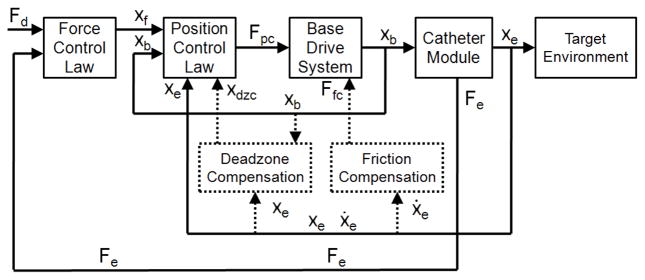
where Kf and Kfi are controller gains and Ke is the approximate stiffness of the environment, which can be estimated from tissue property values in the literature or by an online estimation scheme. This control law is similar to the method presented by Villani et al in [10]. The drive system is commanded to follow the desired position trajectory with a standard PID controller running at 1 kHz. Fig. 6 presents a block diagram of this controller.
Fig. 6.
The block diagram of the force control system. The additional compensation terms are indicated with dotted lines.
A. Compensation Methods
While the control method above improves stability over conventional force control due to the PID position controller, it does not alleviate the tracking errors caused by friction and backlash. These limitations require specific compensation methods, as implemented in [6] and indicated in the block diagram in Fig. 6 by dotted lines.
Friction compensation assumes a Coulombic friction model for the catheter and then feeds forward the friction force Ffc, based on an observer that predicts the velocity [6]. The friction force is determined during operation through an estimation routine and is dominated by the catheter system design (materials, geometry) and sheath configuration (θ).
Backlash compensation adds an additional term to xd that adjusts the desired base position to overcome the deadzone (Fig. 6). The amount of compensation, xdzc, is determined using a catheter-specific deadzone model presented in [6]
| (4) |
where Dsh is the inner diameter of the sheath and Dgw is the diameter of the guidewire. The compensation term xdzc is either added or subtracted from xd based on the direction of target motion and the position of the guidewire relative to the deadzone region.
In certain situations, the model-predicted deadzone width is increased to account for the deformation of the sheath and guidewire caused by large catheter friction [6]. In this study, xdzc was doubled for certain trials to account for the increased deadzone width caused by friction values of over 2 N.
IV. Experimental Evaluation
A. Evaluation Objectives
The force control methods proposed above were evaluated to determine how well the catheter can maintain a desired force against a fast moving target. Based on our previous studies of fast motion compensating with a catheter, the important experimental variables to examine are the catheter bend angle (θ) and the speed and trajectory of the target [6].
B. Catheter Bend Angle Evaluation
The first set of experiments examined the performance of the force control schemes while interacting with a target following a 12 mm peak-to-peak, 1 Hz sinusoidal trajectory in three sheath bend configurations: 0°, 180°, and 360°. The friction, modeled as simple Coulombic friction, increases approximately linearly with bend angle [6]. The friction force Ffc experienced by the catheter guidewire as it moves in the positive or negative directions can be expressed as
| (5) |
As shown in (4), the width of the backlash deadzone is also a function of the bend angle and can be accurately predicted with the deadzone width model first presented in [6].
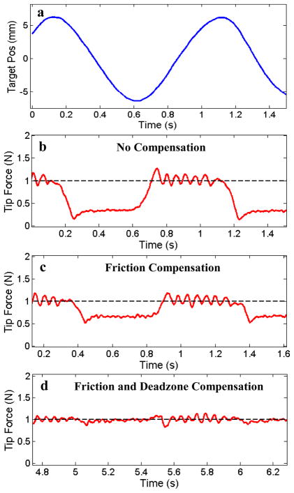
To evaluate the performance of the proposed force control methods, the system was tested with three controller configurations: (1) the force-modulated position controller in eqn. (3), (2) the controller with an added friction compensation term, and (3) the controller with both friction and deadzone compensation terms. The force-modulation gains, Kf and Kfi, were tuned for best stable performance in the first case and kept constant for all of the experiments. Fig. 7 presents a comparison of the controller performance applying a constant force (1 N) against the moving target with the catheter in a 360° bend configuration. The target was covered with a compliant foam with a stiffness of approximately 0.25 N/mm to simulate cardiac tissue.
Fig. 7.
(a) 1 Hz sinusoidal target trajectory and (b) the catheter tip force with only force-modulated position control, (c) with the addition of friction compensation, and (d) with the addition of both friction and deadzone compensation. The bend angle is 360°.
The results in Fig. 7 demonstrate that both friction and deadzone compensation greatly improve the force tracking. Significant tracking errors can be seen when the target changes direction in both Fig. 7b and Fig. 7c. These errors are because the controllers in these plots do not compensate for the deadzone region behavior. Experimentally, this behavior appears as if the tip of the catheter is delayed in responding to the changes in the target trajectory. Deadzone compensation, demonstrated in Fig. 7d, also significantly improves the tracking by adjusting the desired position to remove the backlash effects of the deadzone. Friction compensation improves tracking by cancelling the friction resistance in the sheath, as seen in the improvement in performance between figures 7b and 7c.
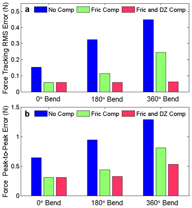
Fig. 8 summarizes the performance results of the three force controllers for each of the three catheter configurations. The average performance of each the controllers, presented in Fig. 8a as the RMS deviation from the desired force, shows that the compensation terms significantly improve the catheter system’s force tracking ability. For example, the RMS error for the 360° bend configuration decreases by over 45% when friction compensated was added and by almost 86% when both friction and deadzone compensated were added.
Fig. 8.
(a) Force tracking RMS error and (b) force tracking peak-to-peak error against a 1 Hz sinusoidal target as a function of bend angle for the three force control methods.
The maximum deviations from the desired force are expressed as the peak-to-peak value, which is the difference between the maximum and minimum tip force value during each experiment. These deviations are often greatest during the changes in the target’s direction of motion (Fig. 7). This data, presented in Fig. 8b, clearly indicates that the compensation methods reduce the deviations from the desired force. For example, friction and backlash compensation decreased the peak-to-peak variations in the 360° bend configuration by almost 60%.
It should be noted that for the 0° catheter bend configuration, the deadzone compensation does not alter the RMS or peak-to-peak values because the catheter system has no deadzone according to the backlash model in eqn. (4).
C. Target Frequency Evaluation
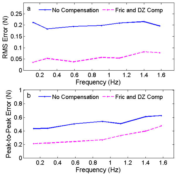
The effect of the frequency of the sinusoidal target was also investigated in this study. The target frequency was varied from 0.1 – 1.6 Hz, approximately the range of heart rates encountered during clinical procedures. The catheter was constrained in a 180° bend configuration and the control system was commanded to maintain a desired force of 1 N with and without friction and deadzone compensation.
The results of these experiments are summarized in Fig. 9. The RMS error for both controllers was approximately constant across the frequency range, with the compensated controller performing roughly 75% better than the uncompensated controller for all of the frequencies. The peak-to-peak error increased as a function of the frequency. This trend is because, as the frequency increases, the speed at which the catheter must travel through the deadzone to maintain the desired force also increases.
Fig. 9.
(a) Force tracking RMS error and (b) peak-to-peak error while tracking a sinusoidal trajectory as a function of the target frequency.
D. Mitral Valve Trajectory Evaluation
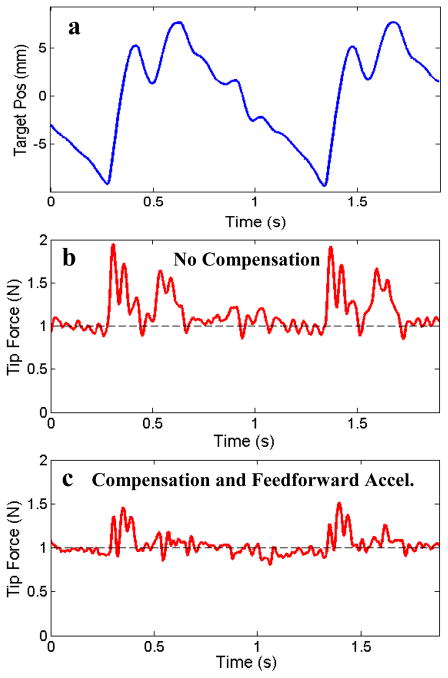
The ultimate goal of the actuated catheter system is to perform surgical repair inside the heart, such as mitral valve annuloplasty [7]. To simulate a mitral valve trajectory, the typical motion of a human mitral annulus was extracted from a series of 3D ultrasound volumes [15]. This trajectory was then used to create a cam mechanism motion simulator. This target follows a more extreme trajectory than the previous experiments, with frequency components as high as 15 Hz and a quick jump of 15 mm in less than 100 ms (Fig. 10a).
Fig. 10.
(a) The mitral valve motion simulator trajectory, (b) the catheter tip force produced with the force-modulated position controller and (c) the controller with friction and deadzone compensation and feedforward acceleration.
The catheter system was commanded to follow the mitral valve simulator while maintaining a desired force of 1 N. Initially, only modest improvements were seen when the compensation terms were added because the controller did not respond quickly enough to the rapid changes in the target trajectory. This tracking error results partly because the reduced position controller gains to maintain force stability and the saturation limits of the actuator.
To improve the trajectory tracking performance, a predictive autoregressive filter was used to estimate the desired catheter acceleration based on observations of previous cardiac motion cycles, as used in several previous robotic beating heart motion compensation systems [18]–[20]. This acceleration estimate was then added to the control law as a feedforward term. This modification allows for the catheter tip to start accelerating at the beginning of the larger jumps in the mitral valve trajectory before large errors develop. In our previous work on ultrasound-guided position-controlled robotic catheter systems, we employed an extended Kalman filter to remove the delays in the 3DUS visual servoing system [5],[7]. This filter can be used to provide the feedfoward acceleration information in vivo to improve the force tracking controller.
Fig. 10 shows the catheter tip force while tracking the simulated mitral valve motion target with and without compensation and the feedforward acceleration term. The tip force RMS error for the system with only force-modulated position control was over 0.26 N. The RMS error for the controller with compensation and feedforward acceleration was 0.11 N, an improvement of about 55%.
V. Discussion
This work elucidates a number of important points that enable effective catheter force control. The first lesson is that the internal performance limitations of the catheter system prevent successful use of simple force controllers. The results show that the catheter performance limitations of friction and backlash need to be compensated for to ensure successful force tracking with the catheter. This finding is especially true as the catheter sheath bend angles increases, thus increasing the size of the deadzone and the amount of friction. These two limitations can only be compensated in the position control domain because they are dependent on the catheter’s position and velocity, which is one of the main reasons for using the force-modulated position controller.
The second lesson from this work is that the portion of the target trajectory that creates the largest deviation from the desired force occurs when the target changes direction. This trend is because the catheter system does not respond instantaneously to the changes in position and force level that occur as the target changes direction. To the authors’ knowledge, this work is the first attempt to control the forces applied by a compliant manipulator with dominant internal friction and backlash on a fast moving target, and the combination of the compensation controller and feedforward acceleration is a novel force control approach.
VI. Conclusions and Future Work
This paper describes a new control method for maintaining a desired force against a fast moving target with a compliant catheter. Friction and deadzone backlash limit the performance of the robotic catheter system. To achieve good force tracking, a force-modulated position controller with friction and deadzone compensation was proposed to overcome the catheter system limitations. These additions reduced the force tracking RMS error by as much as 86%. The system was also evaluated on a mitral valve motion simulator. Because of the mitral valve’s rapid trajectory, the feedforward acceleration was also used to ensure the catheter tracked the jumps in the trajectory. This strategy reduced the RMS error by 55%.
Future work on this project will involve in vivo experiments to show the catheter system’s ability to safely interact with moving cardiac tissue using 3DUS guidance and determine the required force tracking performance. We hope to demonstrate example procedures that require the catheter to maintain a constant force or follow a specific force trajectory on the moving cardiac tissue. The tip force sensor will also be used to improve the surgical outcome by providing the clinician with haptic information about the tissue interactions during a surgical procedure.
Acknowledgments
This work is supported by the US National Institutes of Health under grant NIH R01 HL073647.
Contributor Information
Samuel B. Kesner, Harvard School of Engineering and Applied Sciences, Cambridge, MA, 02138 USA.
Robert D. Howe, Email: howe@seas.harvard.edu, Harvard School of Engineering and Applied Sciences, Cambridge, MA, 02138 USA, Harvard-MIT Division of Health Sciences & Technology, Cambridge, MA, 02139 USA.
References
- 1.Baim DS. Grossman’s Cardiac Catheterization, Angiography, and Intervention. Lippincott Williams & Wilkins; 2005. [Google Scholar]
- 2.Jayender J, Patel RV, Nikumb S. Robot-assisted catheter insertion using hybrid impedance control. Proc of IEEE Int Conf Robotics and Automation. 2006:607–612. [Google Scholar]
- 3.Camarillo DB, et al. Mechanics Modeling of Tendon-Driven Continuum Manipulators. IEEE Trans Robotics. 2008;24:1262–73. [Google Scholar]
- 4.Beyar R. Navigation within the heart and vessels in clinical practice. Annals of NY Academy of Sci. 2010;1188:207–18. doi: 10.1111/j.1749-6632.2009.05102.x. [DOI] [PubMed] [Google Scholar]
- 5.Yuen SG, Kesner SB, Vasilyev NV, del Nido PJ, Howe RD. Medical Image Computing and Computer-Assisted Intervention. Vol. 5241. LCNS; 2008. 3D ultrasound-guided motion compensation system for beating heart mitral valve repair; pp. 711–719. [DOI] [PMC free article] [PubMed] [Google Scholar]
- 6.Kesner SB, Howe RD. Design and Control of Motion Compensation Cardiac Catheters. Proc of IEEE Int Conf Robotics and Automation. 2010:1059–1065. doi: 10.1109/ROBOT.2010.5509250. [DOI] [PMC free article] [PubMed] [Google Scholar]
- 7.Kesner SB, Yuen SG, Howe RD. Proc of Information Processing and Computer-Aided Intervention. Vol. 6135. LCNS; 2010. Ultrasound Servoing of Catheters for Beating Heart Valve Repair; pp. 168–78. [Google Scholar]
- 8.Yuen SG, et al. Robotic Motion Compensation for Beating Heart Intracardiac Surgery. Int J Robotics Research. 2009;28(10):1355–72. doi: 10.1177/0278364909104065. [DOI] [PMC free article] [PubMed] [Google Scholar]
- 9.Siciliano B, Villani L. Robot Force Control. Springer; 1999. [Google Scholar]
- 10.Chiaverini S, Siciliano B, Villani L. A Survey of Robot Interaction Control Schemes with Experimental Comparison. IEEE Trans On Mechatronics. 1999;4(3):273. [Google Scholar]
- 11.Eppinger SD, Seering WP. Introduction to Dynamic Models for Robot Force Control. IEEE Control Sys Magazine. 1987:48. [Google Scholar]
- 12.Eppinger SD, Seering WP. AI Memo No 948. Mass. Inst. of Tech., Artificial Intelligence Lab; 1987. Understanding Bandwidth Limitations in Robot Force Control. [Google Scholar]
- 13.Maples JA, Becker JJ. Experiments in Force Control of Robotic Manipulators. Proc of IEEE Int Conf Robotics and Automation. 1986:695–702. [Google Scholar]
- 14.Yuen SG, et al. Proc of Int Conf on Medical Image Computing and Computer-Assisted Intervention. Vol. 5761. LNCS; 2009. Robotic Force Stabilization for Beating Heart Intracardiac Surgery; pp. 26–33. [DOI] [PMC free article] [PubMed] [Google Scholar]
- 15.Kettler DT, et al. An active motion compensation instrument for beating heart mitral valve surgery. Proc of IEEE/RSJ Int Conf Intelligent Robots and Systems. 2007:1290–95. [Google Scholar]
- 16.Webster JG. Tactile Sensors For Robotics and and Medicine. John Wiley & Sons, Inc; New York: 1988. [Google Scholar]
- 17.Townsend W, Salisbury J. The Effect of coulomb friction and stiction on force control. Proc of IEEE Int Conf Robotics and Automation. 1987:883–889. [Google Scholar]
- 18.Chatfield C, editor. The Analysis of Time series: An introduction. Chapman & Hall; London: 1992. [Google Scholar]
- 19.Bebek O, Cavusoglu M. Intelligent control algorithms for robotic assisted beating heart surgery. IEEE Trans Robotics. 2007;23:468–480. [Google Scholar]
- 20.Yuen SG, Novotny PM, Howe RD. Quasiperiodic predictive filtering for robot-assisted beating heart surgery. Proc IEEE Int Conf Robotics and Automation. 2008;2008:3875–80. [Google Scholar]


