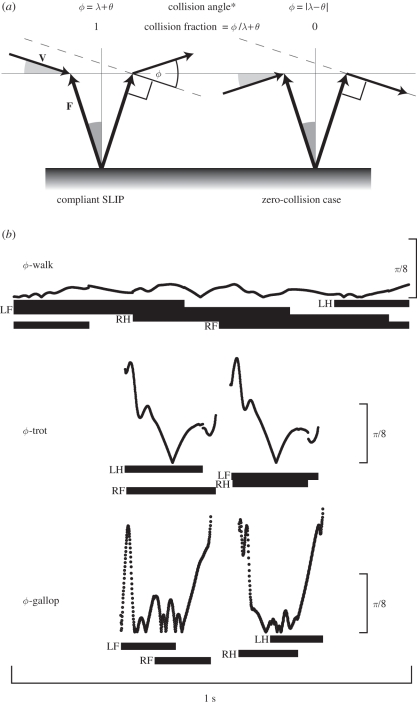
Figure 1.
(a) Planar illustrations of collision-based mechanics showing instantaneous angles. The force angle θ (equation 2; dark grey) is the magnitude of the angle between the force vector F and the vertical axis, and the velocity angle λ (equation 4; light grey) is the magnitude of the angle between the velocity vector V and the horizontal axis in the direction of travel. Collision angle ϕ is determined from the dot product of the force and velocity vectors (equation 6). The asterisk denotes trigonometric two-dimensional solutions to ϕ as these special cases are provided in an online supplement but only the equations of table 1 are used in our analysis. In these examples of compliant SLIP and idealized zero-collision cases, the magnitudes of all force and velocity angles are the same but their collision fractions represent opposite extremes. (b) Plots of instantaneous collision angle ϕ (in radians) versus time are drawn to the same scale for walking, trotting and galloping sample data from a dog. Footfall patterns are represented as horizontal bars beneath each plot with footfalls labelled as left hind (LH), left fore (LF), right hind (RH) or right fore (RF).

