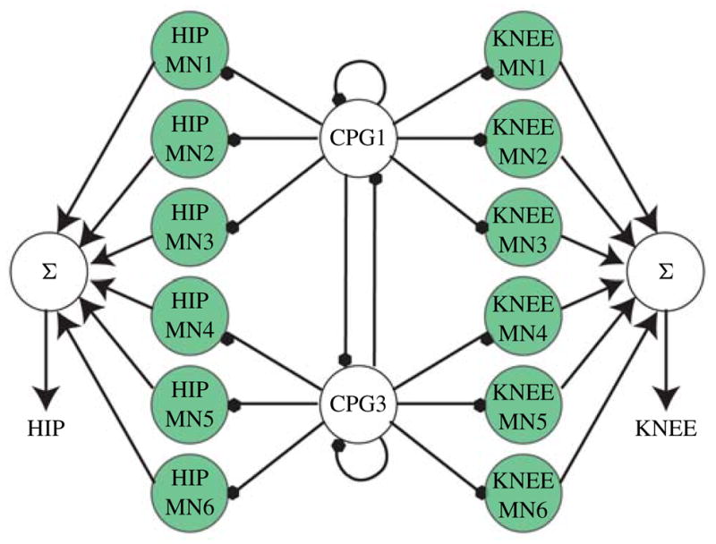
Fig. 7.

Initial topology used to control the shape of the joint angle profiles. To avoid clutter, only the motor neurons for the left side are shown. The circuit would look almost identical for the right side, except that CPG1 and CPG2 would be swapped around to cause a 180° phase shift. At the beginning of this stage of evolution, we introduce six motor neurons (shaded neurons) per joint. Motor neurons with little or no contribution (low summation weights) are later removed from the network to conserve computational resources. Each final summation weight can be positive or negative as determined by the optimization process.
