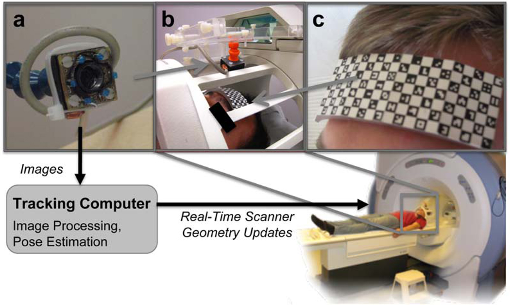
Figure 1.
Setup of the optical motion correction system: the MR compatible camera (a) was mounted on the 8 channel head coil (b). Reliable features for optical tracking of the patient were provided by the self-encoded marker (c). During data acquisition the camera signal was processed by an external tracking computer to estimate the pose updates. These were sent to the MR scanner via network connection to adjust gradient and RF hardware controller for prospective motion compensation in real time.

