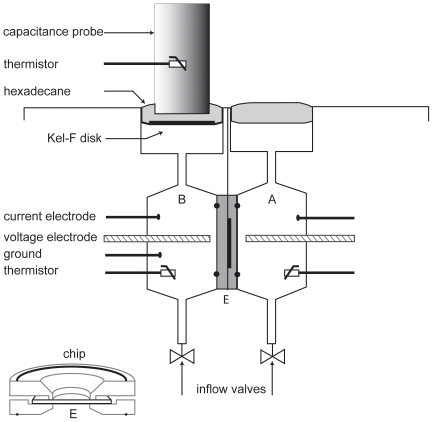
Figure 2. Schematic diagram of fluid transport chamber.
Top part of figure shows internal chamber design consisting of two identical hemichambers. Each hemichamber has a voltage-sensing electrode, three current-passing electrodes, and a thermistor. Hemichamber A contains media bathing the apical or retinal surface; hemichamber B contains solution bathing the basal or choroidal surface. Surface of each bathing solution is covered with hexadecane to eliminate evaporation. A capacitance probe is immersed in the hexadecane in one hemichamber. Volume change is detected by changes of distance between probe and bathing media surface. Solutions are exchanged by gravity flow from reservoirs through inflow valves at the bottom and suction from the surface on top. A thin Kel-F disc (dark horizontal line) is used to isolate probe tip from media and avoid short circuit. RPE monolayer (E) is mounted between two circular Kel-F discs with O-rings (shown in lower left corner of the figure). This chip is mounted between two water-jacketed Kel-F blocks in main chamber located in a modified CO2 incubator (5% CO2, 36.5°C) for fluid transport (Jv) measurements.

