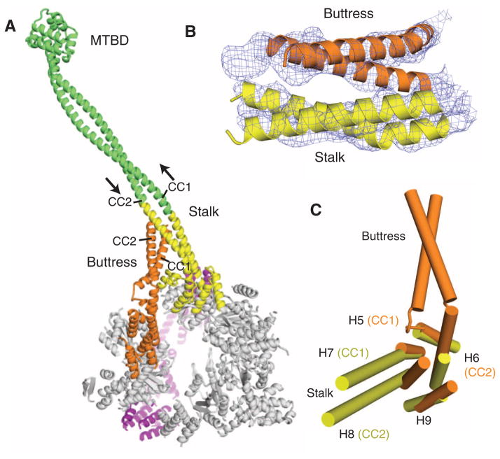
Fig. 5.
The stalk and buttress coiled coils. (A) The motor domain, highlighting the stalk and buttress, viewed from the C-terminal face. The stalk from this crystal structure is highlighted in yellow, and the green extension is a continuation of the stalk modeled with an antiparallel coiled coil of the proper length. The MTBD and distal coiled coil is from a previously solved crystal structure (PDB code 3ERR). (B) The experimental electron density map (1 σ contour) and model showing the likely interaction of the distal part of the buttress with the stalk. (C) The small domains of AAA4 and AAA5 show that H7 and H8 extend into the stalk coiled coil, and H5 and H6 extend into the buttress coiled coil.

