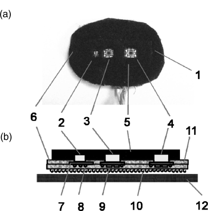
Figure 3.
Structure and positioning of a NINscan probe. (a) photo of the probe pad. (b) structure of the probe and the soft fixation band (side view). 1. Probe. 2. Dual wavelength light source. 3. First optical detector. 4. Second optical detector. 5. Black filling material. 6. Probe base material. 7. Circuit board. 8. Leads and wires. 9. Electronic components on the circuit board. 10. Velcro bottom surface. 11. Adhesive top surface. 12. Fixation band.

