Abstract
Imaging microchannel plate (MCP) detectors with cross strip (XS) readout anodes require centroiding algorithms to determine the location of the amplified charge cloud from the incident radiation, be it photon or particle. We have developed a massively parallel XS readout electronic system that employs an amplifier and ADC for each strip and uses this digital data to calculate the centroid of each event in real time using a field programmable gate array (FPGA). Doing the calculations in real time in the front end electronics using an FPGA enables a much higher input event rate, nearly two orders of magnitude faster, by avoiding the bandwidth limitations of the raw data transfer to a computer. We report on our detailed efforts to optimize the algorithms used on both an 18 mm and 40 mm diameter XS MCP detector with strip pitch of 640 microns and read out with multiple 32 channel “Preshape32” ASIC amplifiers (developed at Rutherford Appleton Laboratory). Each strip electrode is continuously digitized to 12 bits at 50 MHz with all 64 digital channels (128 for the 40 mm detector) transferred to a Xilinx Virtex 5 FPGA. We describe how events are detected in the continuous data stream and then multiplexed into firmware modules that spatially and temporally filter and weight the input after applying offset and gain corrections. We will contrast a windowed "center of gravity" algorithm to a convolution with a special centroiding kernel in terms of resolution and distortion and show results with < 20 microns FWHM resolution at input rates > 1 MHz.
Keywords: Microchannel plate detectors, Single-photon counting, Cross strip anodes, Centroiding algorithms
1. Introduction
Imaging MCP detectors require a method to determine the centroid of the charge clouds that exit the plates for each MCP amplified event that was generated by an input photon or particle. One such method is a crossed-strip anode, where two perpendicular sets of long, narrow electrodes sample the spatial distribution of the charge events exiting the MCPs[1, 2]. Each electrode charge signal is amplified and digitized independently, and the centroid of the distribution is calculated using an optimized algorithm that resides in the firmware of an FPGA.
There are competing tradeoffs in choosing the right algorithm. The required precision of the centroid determination to achieve the desired spatial resolutoin is sometimes at odds with the accuracy of the determination, where various non-linearities in the calculation can cause image distortions. High event rates require higher bandwidth to maintain througput, thus affecting both precision and accuracy. Finally, the overall algorithmic complexity can easily exhaust existing FPGA resources, (though this can sometimes be solved by waiting for the next FPGA upgrade).
In previous papers [3, 4, 5], we have demonstrated the performance of XS readouts that can achieve very high spatial resolution (< 6 microns FWHM) using low noise amplifiers and laboratory ADCs with the centroiding calculations done inside the computer. We have since replaced the ADC/computer system with the Parallel Cross Strip (PXS) electronics [5] which consists of 64 × 12 bit ADCs continuously sampling their inputs and transferring their outputs to a Virtex 5 FPGA via 300MHz double edge LVDS outputs. For a 22 mm XS anode, we use a single 64 channel PXS box, as there are 32 strips per axis. For the larger 47mm anode (supporting a 40mm effective input diameter), we use two PXS boxes, one for each axis, which have to be synchronized for each event.
2. Event Logic
In a massively parallel system such as the PXS box, data is flowing into the FPGA at 50 megasamples per second with 64 channels at 12 bits each which corresponds to 38 gigabits/second. Firmware was developed to take this data stream and detect event charge clouds, determine their spatial and temporal locations and transfer the X,Y,T event list information to a downstream computer for storage and/or subsequent histograming. A partial list of the steps that this firmware does to accomplish this goal include:
Remap channel numbers such that they match the proper anode locations
Subtract fixed DC offsets found in calibration
Detect an event by requiring a positive slew greater than a threshold level. The FPGA is continuously calculating the slew by taking the difference from one clock cycle to the next on every channel.
Of the channels with a slew, find the approximate center channel
Take a subset of channels centered on the channel of step 4, and send this data to the math module
Linearize the amplitudes with 2 parameters based on the charge amp gain calibrations. A quadratic term is added (parameter 1) once the signal reaches a certain saturation voltage (parameter 2).
Apply a finite impulse response (FIR) [6] filter to the event pulse to improve the SNR of the amplitude determination in each channel.
In parallel, apply another FIR filter to determine the event time of arrival, similar to a digital constant fraction discriminator to achieve sub-clock cycle time resolution
Calculate spatial centroid using algorithms which weight the channel amplitudes appropriately.
Correct the calculated X,Y centroid distortion using a look up table that is based on the algorithm and calibrations
Synchronize (X,Y,T) position into a FIFO
Transfer events to downstream computer
Clearly, this logic is pipelined and taking place concurrently at a 50MHz clock cycle. There are some steps that result in a deadtime per event. The slew detect requires a minimum of 2 clock cycles (40ns). In parallel with this is the amplitude FIR filter. If we use 4 clock cycles of data to determine an event amplitude, we cannot have another event within 4 clock cycles or 80ns. Such a system could accommodate an output rate of 1.25 million counts per second at 10% deadtime. However, given the 160ns fall time of the charge amplifiers, events can “collide” temporally and result in a miss-analyzed event. To filter out these events, we have added a pileup rejection module to the event logic, that will reject any event preceded by a previous event in a settable window, typically 160ns.
3. Centroiding algorithm
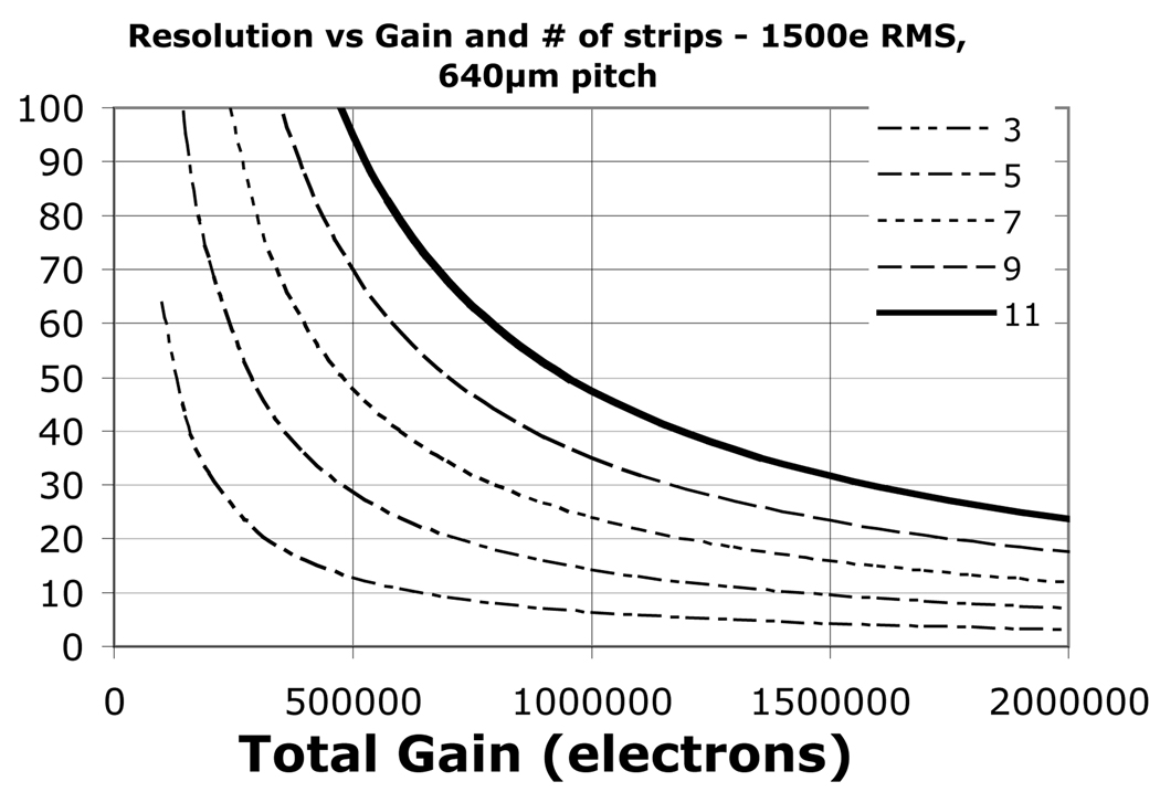
Much work has been done to find the best algorithm for XS readouts [7], but simply stated, given a fixed noise per measurement, the less strips used in the calculation, the more precise the centroid location is determined (better spatial resolution). However, the more strips used in the calculation, the more accurate (less distortion) the centroid result. Fig. 1 shows the dependency of the spatial resolution vs. gain for the number of strips used in a simple “center of gravity” type algorithm and a fixed noise per strip consistent with our 47mm anode and the Preshape32 amps.
Fig. 1.
Simulated spatial resolution vs. MCP gain with different curves representing the number of strips used in the centroid calculation. The assumed noise and strip period is for the 40 mm XS detector
If you decide to limit the number of strips in a calculation, you must carefully consider the criteria for which strips you use. Excluding or including a strip signal in a standard centroid calculation will move the location of the centroid. An algorithm with an odd fixed number of strips will always have a discontinuity at strip boundaries where the charge is distributed evenly between the strips on either side of the centroid. The odd strip out will either be on the right side or the left side of the event charge distribution, depending on noise fluctuations, resulting in a discontinuity or region of avoidance. For an even number of strips, the discontinuity appears at the location of the strip centers.
Our standard algorithm is what we call the “all above threshold” (AAT) algorithm, where only strip signals above a settable fraction of the total event charge are used in the centroid calculation. After an event’s spatial peak strip is identified, a quick sum of the nearest neighbours is performed. A small fraction of this sum (typically 3%) is subtracted from all channels, with those strips on the wings of the distribution whose resultant signals are negative set to zero. If a channel was slightly above threshold, it is now close to zero, so the channels on the wings of the distribution do not have a strong affect on the centroid determination. This algorithm effectively “adjusts” the number of strips used, depending on the location of the charge cloud: an even number of strips for events near strip boundaries, and an odd number for events near strip centers.
The resultant error in the centroid position as a function of centroid location causes a periodic distortion in the effective pixel size which leads to periodic undulations in a uniformly distributed flat field. As the detector plate scale (in pixels/mm) is the derivative of the mapping of the true spatial scale to calculated spatial scale, a small distortion in position determination can cause a rather large flat field undulation. For example, a 6 micron amplitude sinusoidal error across a 600 micron period (12 microns or 2% peak to peak) will cause a flat field to modulate by 12% (2% times 2π).
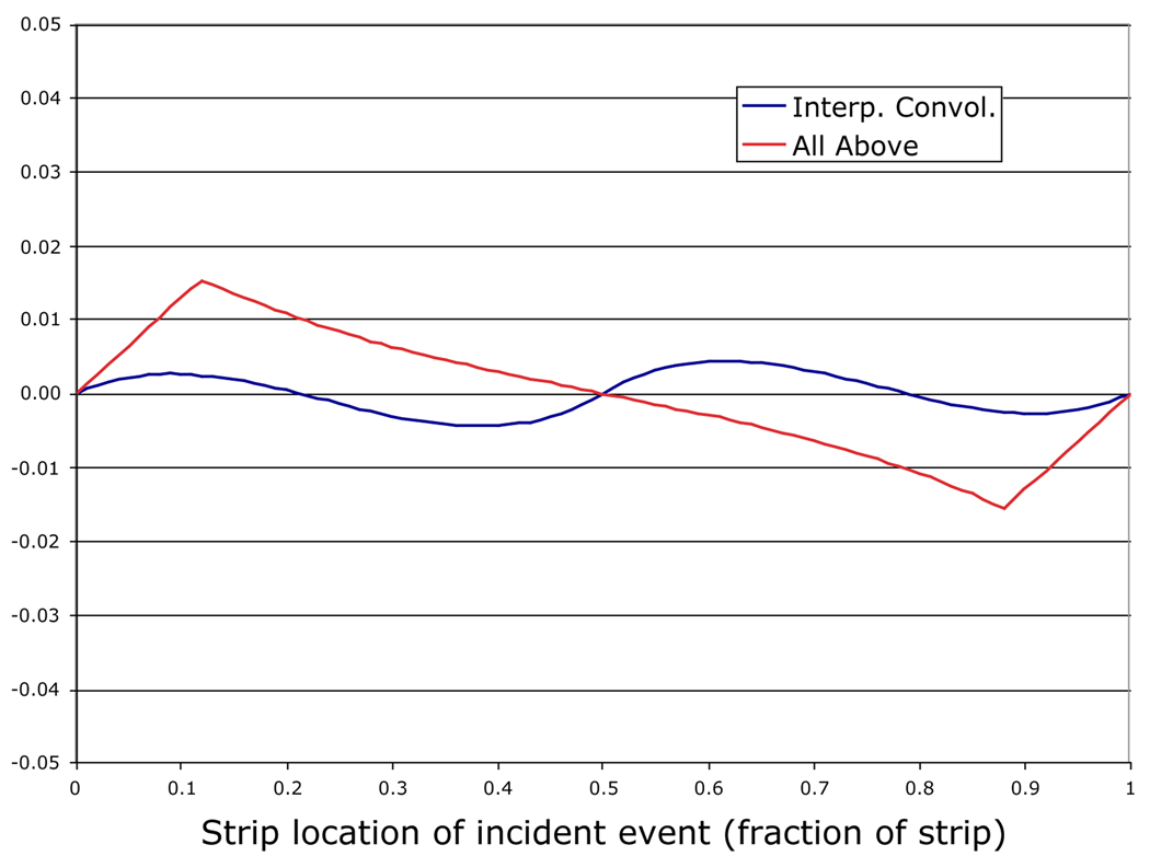
We have simulated these algorithmic distortions by assuming our charge clouds have gaussian shapes of varying widths and amplitudes (in units of strip periods). We then calculate the centroids the algorithms produce as a function of the true input location across the strip. Fig. 2 shows the difference in calculated vs. true position in units of strip pitch for both the AAT algorithm and the Interpolated Convolution” (IC) algorithm described below.
Fig. 2.
Simulated centroid error vs. input position on strip (in units of strip pitch) for two different algorithms. The input gaussian charge cloud had a 1 sigma width of 0.8 of the pitch.
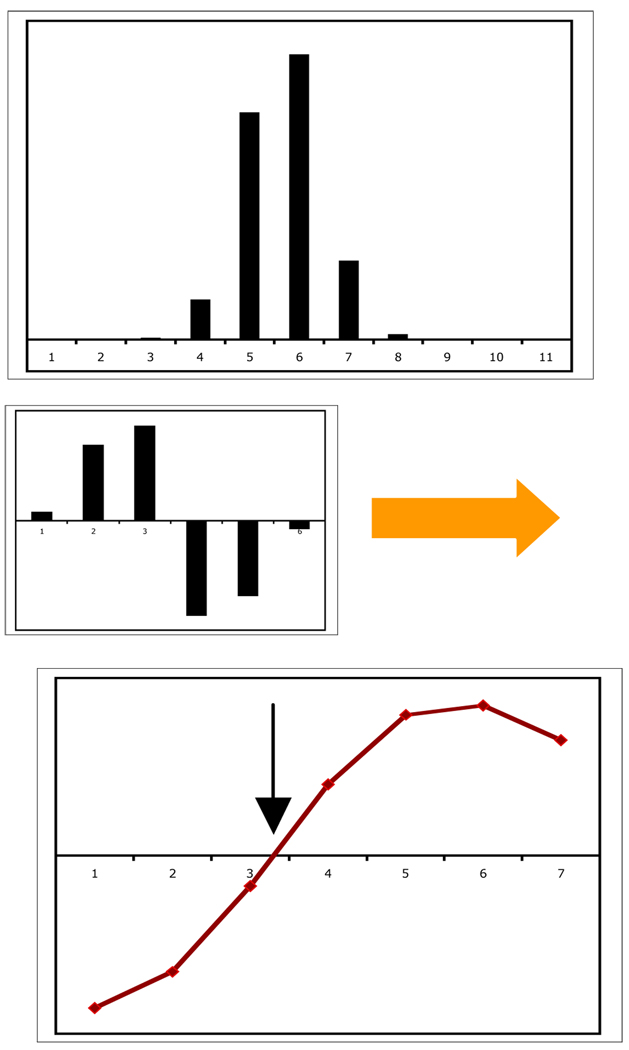
The IC algorithm uses a different technique to find the center of the spatial distribution. It convolves the charge distribution of the strips with a bipolar kernel derived from the derivative of the average charge distribution. The zero crossing of the (discrete) convolution is interpolated to a sub-strip position and is interpreted as the centroid location of the charge cloud (Fig. 3). This method has the advantage of being insensitive to any baseline shifts because the kernel sums to zero. The kernel is also a matched-filter as it is based on the average charge distribution, so it weights the higher signal to noise strips accordingly. We have found with simulations that the distortions of the IC algorithm are continuous and smooth (Fig 2) which allows easier corrections with a look-up table, and that the spatial resolution is better than the AAT algorithm, most likely due to the weighting of the strips with better SNR.
Fig. 3.
Interpolated convolution algorithm example. The top diagram represents a sampled charge cloud distribution. A fixed kernel (center), which is a discrete differentiated gaussian of the same width as the charge cloud, is convolved through the charge cloud data to produce the resultant convolution points (bottom). The interpolated zero-crossing (arrow) represents the charge cloud location.
4. Results
The PXS electronics were run with two XS detectors: an18mm active area optical tube with a 22 mm round anode of 32 strips in each axis and a 40mm active area detector readout with a square 47mm anode of 72 strips per axis, of which we used 64 per axis.
4.1. Spatial Resolution
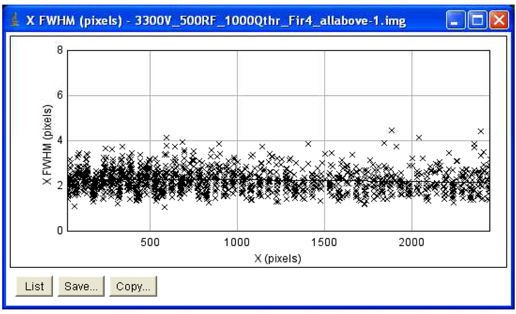
Using the larger 40 mm XS detector, we placed an array of 10 microns pinholes directly on the front surface of the MCP and illuminated with 253nm UV light. Fig. 4 is a plot of the derived spatial resolution (FWHM) vs. the X position after fitting each spot with a gaussian distribution. The average of all the spots is 22 microns at a gain of 900000 e-per photon, consistent with Figure 1.
Fig. 4.
Spatial resolution (FWHM) of 4500 spots of a pinhole grid vs. the X dimension for the 40mm XS detector. A pixel is 10 microns and the average is 22 microns.
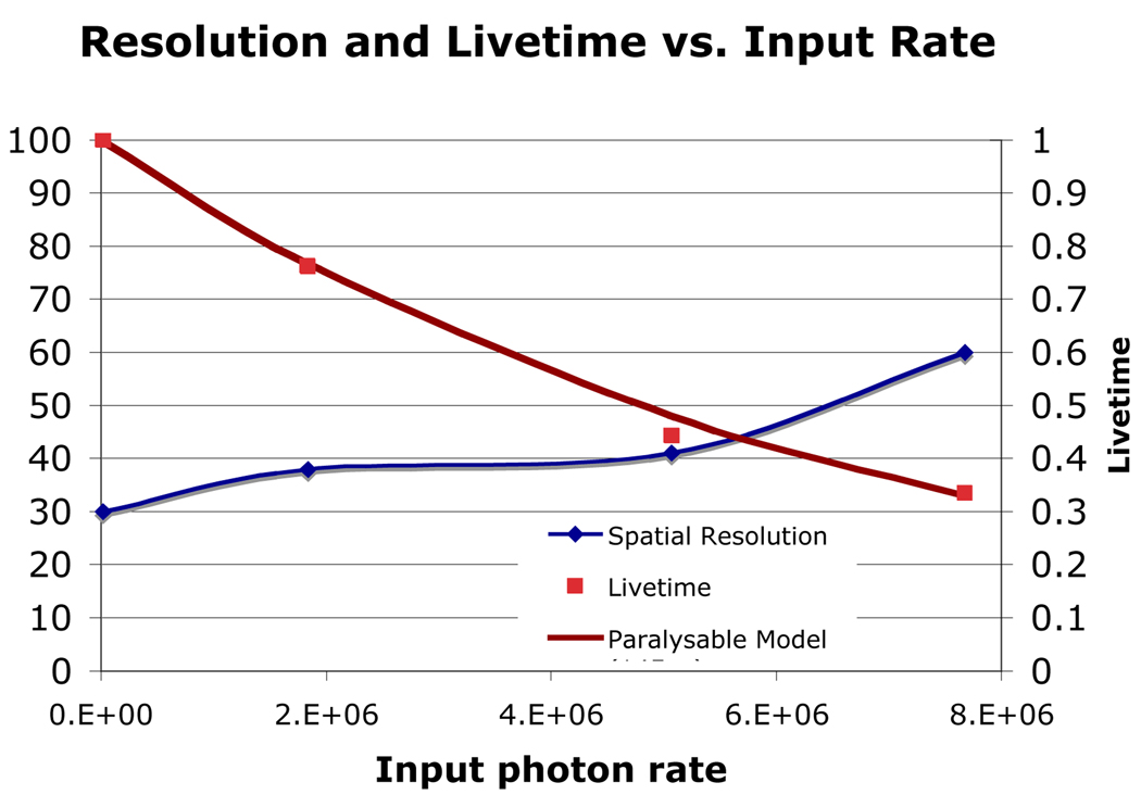
For the 18 mm image tube, we could not restrict the input light to 10 micron holes, as the MCP was inside the vacuum tube. Rather we projected an array of optical spots using a lens and achieve a typical resolution of 30 microns, most likely limited by the proximity-focused photocathode. However, this configuration allowed us to increase the diffuse count rate arbitrarily and measure the resolution as a function of count rate. Fig. 5 shows the measured resolution of a single spot vs. input count rate, as well as the measured livetime of the detector at these rates.
Fig. 5.
Spatial resolution of 18 mm XS optical tube vs. input diffuse photon rate. Also shown is the livetime (right axis) vs. the input rate. The solid line through the livetime points is the predicted livetime assuming a paralysable deadtime per event of 160 ns.
4.2. Algorithm induced distortion and its correction
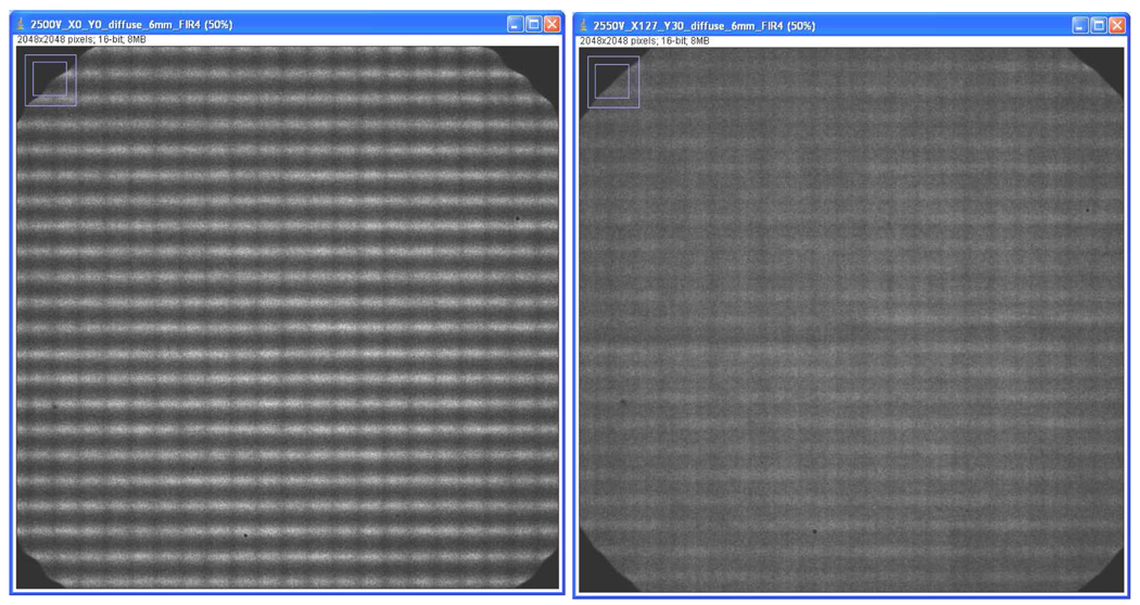
An example of the periodic distortion caused by the undersampling of the charge distribution is shown in Fig. 6 (left side) for the 40 mm detector. In this case the charge cloud was adjusted to be very small by a large accelerating field behind the rear MCP. From this flat field we could derive the correction factors to remap each event (x,y) to a corrected (x',y') coordinate based on its measured sub-strip position. This is done as a simple look-up table by the FPGA right before transfer of each event to the downstream computer. The resulting corrected image is shown in Fig. 6.
Fig. 6.
UV flat field image of the 40mm XS detector. The flat field on the left has an extreme periodic distortion caused by a narrow charge cloud exiting the rear MCP resulting in undersampling of the charge distribution. A correction is applied to every event in real time which gives the corrected image on the right.
5. Conclusions
We have presented a brief overview of our XS detector and electronics based on a massively parallel architecture that can achieve high spatial resolution at high count rates. Centroiding algorithms have been developed that can operate in a fast, real time FPGA pipeline, and techniques have been tested to reduce or remove the small distortions inherent in undersampled data. Currently, the ultimate capabilities of this system are limited by the front end Preshape32 ASIC, which was designed ~15 years ago. New ASICs have been proposed to decrease significantly both the event duration and amplifier noise.
Acknowledgments
We wish to thank Dr. Xavier Michalet for the use of his 18mm XS detector. Portions of this work were supported by NASA under Grants NNG05GC79G and NNX08AE04G, NSF Grant DBI-0552-099 and NIH grant NIBIB EB006353.
Footnotes
Publisher's Disclaimer: This is a PDF file of an unedited manuscript that has been accepted for publication. As a service to our customers we are providing this early version of the manuscript. The manuscript will undergo copyediting, typesetting, and review of the resulting proof before it is published in its final citable form. Please note that during the production process errors may be discovered which could affect the content, and all legal disclaimers that apply to the journal pertain.
References
- 1.Siegmund OHW, Tremsin AS, Vallerga JV, Hull J. IEEE Trans. Nucl. Sci. 2001;48:430. [Google Scholar]
- 2.Siegmund OHW, Tremsin AS, Vallerga JV, Abiad R, Hull J. Nucl. Instr. And Meth. 2003;A 504:177. [Google Scholar]
- 3.Tremsin AS, Siegmund OHW, Vallerga JV, Hull J. IEEE Trans. Nucl. Sci. 2004;51(N4):1707. [Google Scholar]
- 4.Tremsin S, Siegmund OHW, Vallerga JV, Raffanti R, Weiss S, Michalet X. IEEE Transactions on Nuclear Science. 56(2009):1148. doi: 10.1109/TNS.2009.2015302. [DOI] [PMC free article] [PubMed] [Google Scholar]
- 5.Siegmund OHW, Tremsin AS, Vallerga JV. Proc. SPIE. 2009;7435 in press. [Google Scholar]
- 6.Haddad KC, Stark H, Galatsanos NP. Circuits and Systems II -Analog And Digital Signal Processing. IEEE Trans. 2000;47:714. [Google Scholar]
- 7.Tremsin AS, Vallerga JV, Siegmund OHW, Hull JS. Proc. SPIE. 2003;5164:113. [Google Scholar]


