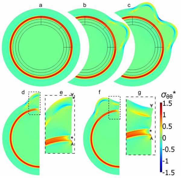
Figure 7. Finite element model for cortical folding caused by phased differential growth.
(a-c) Model geometry and stress distribution after each major simulation step (i-iii, see Methods), leading to the formation of two gyri in designated regions. (d-g) A section of the model shown in (c) was used to simulate the effects of subsequent radial cuts within a gyrus (d,e) and a sulcus (f,g). The simulated cuts from the cortical surface through the subcortical white matter tract are indicated by pairs of arrowheads, and resulting openings are indicated by asterisks. (Panels e and g are close-ups of the dashed regions in d and f, respectively.) Colors indicate circumferential stress (σθθ*) normalized relative to the material shear modulus.

