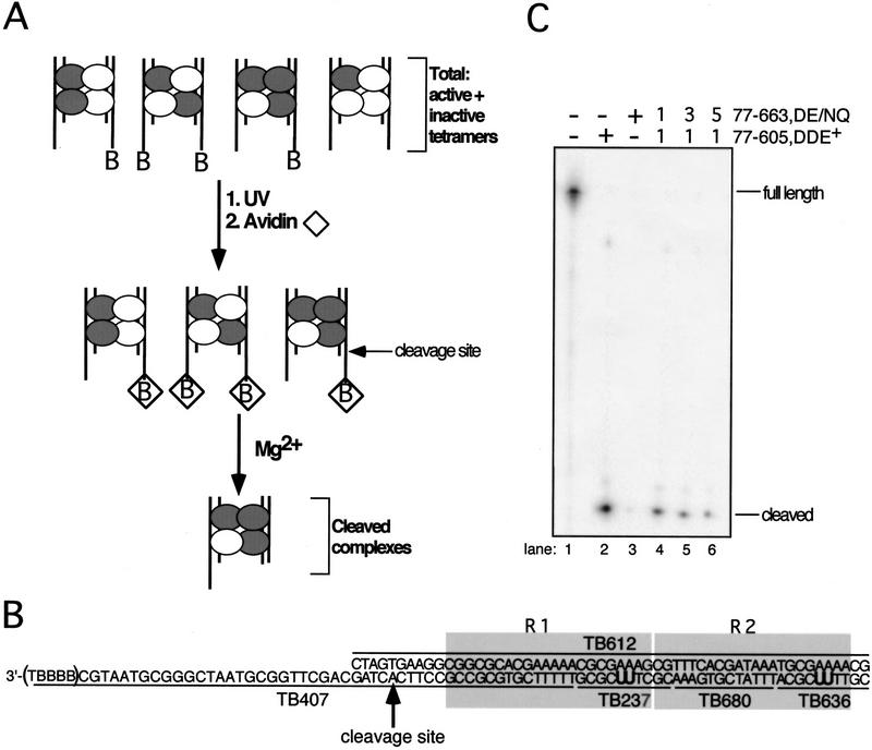
Figure 1.
Schematic of experimental and substrate designs. (A) Transpososomes containing DDE+ (white circle) and DDE− (gray circle) transposase subunits and the nonbio and bio (denoted by B in figure) Mu DNA end substrates (vertical lines) were assembled in Ca2+. Transpososomes containing a bio substrate were then immobilized on an avidin matrix (⋄). The addition of Mg2+ allowed hydrolysis by transposase, and complexes that catalyzed cleavage of the bio substrate were released from the avidin matrix. Although mixed tetramer complexes that contained two bio substrates could be released from the matrix, the majority of released complexes contained one nonbio and one bio substrate in these experiments (data not shown). (B) Mu DNA end substrates. Molecules containing the R1 and R2 MuA-binding sites (shaded boxes) were made by annealing the indicated single-stranded oligonucleotides. The bio substrate is shown; the nonbio substrate lacks the five 3′ nucleotides (TBBBB) of TB407. Oligonucleotides TB237 and TB636 contained two cross-linking nucleotides (U) that replaced two thymidines in the natural DNA sequence; these oligonucleotides are individually 32P-phosphorylated at their 5′ ends to label subunits bound to the R1 and R2 sites, respectively, upon cross-linking. All unlabeled oligonucleotides within each substrate contained a 5′ OH. The adenosine directly 5′ to the phosphodiester bond that is cleaved by transposase is indicated by the arrow. (B) Biotin-dT; (U) 5-iodo-2′-deoxyuridine (IdU in text). (C) Denaturing PAGE analysis of the bio substrate in complexes released from the matrix; oligonucleotide TB407 was 32P-phosphorylated at its 5′ end. Numbers above lanes 3–5 indicate the molar ratio of DDE+ to DDE− transposase included in the initial reaction.

