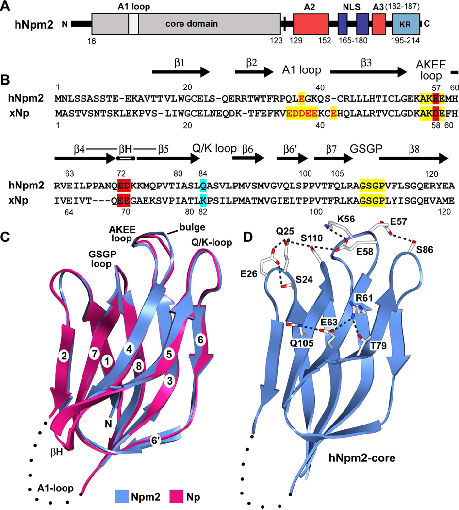
Figure 1. Domain organization, sequence alignment and monomer structure of Npm2.
(A) The domain architecture of Npm2 is shown with acidic tracts colored in red, the bipartite NLS in blue and a C-terminal, basic KR rich region in light blue. (B) A sequence alignment for Npm2- and Np-core domains is shown with β-strands indicated by black arrows. Important loops are highlighted in yellow, acidic residues are shown in red and additional residues that may participate in decamer formation are highlighted in cyan. (C) The Npm2-core subunit is shown as a ribbon diagram (in blue), over-layed onto Np-core (in red). The position and approximate size of the A1-loop is indicated by a dotted loop and the β-hairpin of Np is labeled (βH). A bulge in the AKEE-loop is present relative to the equivalent AKDE-loop of Np. (D) A salt bridge network extends across the top surface of the Npm2-core domain. In addition, hydrogen bonds are also present between Glu57 and Ser86 and a second network is formed on the external face centered on Glu63. Ribbon figures were made with Chimera. 37

